Hi,
I am trying to compute the complete set of losses in high-speed electrical machines. This post can be used as a tutorial for all other machine designers who want to simulate complete losses. As the software can easily calculate copper loss, the focus is only on AC and DC losses associated with the windings.
- 2D simulations
Can you please explain what the best way to calculate copper loss is? The candidates for 2D simulations are:
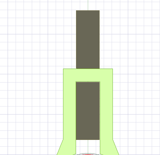
1.1 Changing to transient simulations. Drawing a rectangle in the slots, and setting them to stranded coils in the excitation menu, assigning the number of coils. Adding winding and set the currents and add coils under them. Running the simulations and plot stranded loss.
The problem with this strategy is that using the number of strands, the software simply devices the copper surface drawn with the number of coils and uses it in the ro*L/A for the resistance of the copper wire. It means, you cannot use fill factor for the copper surface and the software will use all the surface drawn. Do you have any solutions to compensate for using fill factors? Or we should actually by hand calculate each wire surface, then work out the surface, multiply it by the number of coils and try to draw the copper surface in a way to be equal to the calculated surface by hand overall? Also, AC losses are not taken into consideration. Skin effect is not also considered. end effects are not also considered.
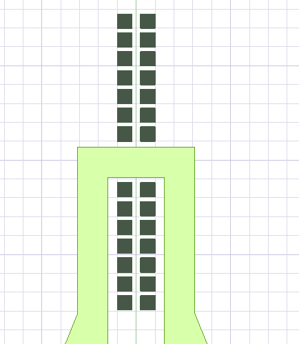
1.2 Changing to transient simulations. Drawing each coil separately, and setting them to soli coils in the excitation menu, Adding winding, and setting the currents. Running the simulations and plotting solid loss.
The problem with that is that it is so time-consuming. Also, AC losses are not taken into consideration. Skin effect is not also considered. end effects are not also considered. How can we take them into consideration?
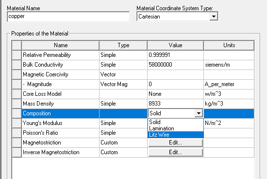
P.S: Maybe someone like me does not want to use Litz wire because Litz wire is not actually used in the real machine, but if the person answering this question want to use litz wire as a solution to account for the skin depth, please say so with an example of how to actually use litz wire configuration in the material library rather than solid.
2. 3D simulations
2.1 The candidates for 3D simulation are the same as the 2D. With the effect of end winding drawn. But again the problem with AC resistance loss(skin and proximity) still lingers. Also, the copper surface problem also exists he same with 2D simulation.
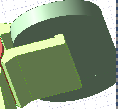
2.2 Same with the 2D, we can simulate each coil as well. The problem with that is that it is so time-consuming. Also, AC losses are not taken into consideration. Skin effect is not also considered. end effects are not also considered. How can we take them into consideration?
I would appreciate anyone answering this question.


