Photonics

Photonics

Topics related to Lumerical and more.

2D inverse design grating coupler

    • rahul.sanghvi
      Subscriber

      In step 2 of 2D grating coupler design, how is the sweep length determined ?

      I was expecting the source sweep would be carried out over the entire length of the grating, but in the example file it sweeps from 4 µm to 7 µm only. 

    • anna.wirth-singh
      Ansys Employee

      Hi Rahul,

      Thanks for your question. Could you please clarify which example you are working with? We have a few grating coupler design examples, so I want to check that I am looking at the right one to answer your question. 

      We have one here using the built-in particle swarm optimization tool: Grating coupler – Ansys Optics

      This one uses the Python-based inverse design package lumopt: Inverse Design of Grating Coupler (2D) – Ansys Optics

      For a sweep over source position, there is typically a well-defined maximum. The sweep over source position probably looks something like this, where the y-axis is the transmission into the waveguide and the x-axis is the source position:

      For this parameter, it is clear that the optimal value is somewhere near the center. Most likely, the designer of the example file restricted the sweep range so that they could run fewer points (and therefore get results faster), with the knowledge that the optimal value would not be near the endpoints of the sweep. 

    • rahul.sanghvi
      Subscriber

      Hi Anna, 

      I am refering to the inverse design example: https://optics.ansys.com/hc/en-us/articles/360042800573-Inverse-Design-of-Grating-Coupler-2D

      and the code "pid_grating_coupler_sweep_2D.py" in the second step. 

      I am not able to follow how did the designer define the start and the end point of the sweep. I would like to determine the transmission over the entire length of the grating. 

    • rahul.sanghvi
      Subscriber


      Hi Anna, 

      I am wondering if you could help me out with implementing optimisation based FDTD simulations on university supercomputer.

      Currently, I am using a desktop where I open the lumerical GUI and load a python file in the “script file editor” section and execute it. 

      To implement this on the supercomputer, we do not have a visual node where I can do the same process.
      Can you suggest a method where I run this python file in the supercomputer terminal and it somehow does the FDTD simulation


    • anna.wirth-singh
      Ansys Employee

      Hi Rahul,

      Thanks for the additional information. For your first question regarding the sweep, the script “pid_grating_coupler_sweep_2D.py” is calling a sweep that is defined in the base Lumerical file "pid_grating_coupler_2D_TE_base .fsp". Specifically, if you look at line 85 in the Python script, it uses runsweep - Script command – Ansys Optics to run the sweep that has previously been defined in the base Lumerical file. So the sweep endpoints are set in the base Lumerical file. On the ‘Optimizations and Sweeps’ tab, you should see the sweep ‘sweep source position.’ From there, you can edit the values that are included in the sweep. This is illustrated in the screenshot below:


      Regarding your second question about running FDTD on a high-performance computer, I can direct you to some resources to get started. Please see this page for a general overview: Introduction to High-Performance Computing with Lumerical – Ansys Optics

      It sounds like you will be running on a local cluster, so this page Running Lumerical on a Local On-premise Cluster – Ansys Optics contains instructions in how to set this up.

      Best,

      Anna

    • rahul.sanghvi
      Subscriber

      Hi Anna,

      Thanks for explaining. The first answer regarding sweep is clear.

      Regarding the cluster, the given example describes about a sweep where the .fsp files are created, saved and then FDTD is performed. How can I run the file "pid_grating_coupler_2D_1etch.py" in the same way ?

      It does not create any .fsp file but performs FDTD upto 100 iterations (or any user defined number) to optimise the grating structure. In this case, how can I perform this optimsation on HPC.

    • rahul.sanghvi
      Subscriber

      Hi Anna,

      Looking forward to hearing from you.

      Thanks in advance


    • Lito
      Ansys Employee

      @rahul.sanghvi,

      To run Python API will require a GUI connection and a GUI license. >>Python API overview – Ansys Optics

      If you do not have a GUI connection (headless Linux system); 

      Hope this helps. 

      Lito

    • rahul.sanghvi
      Subscriber

      Hi Lito,

      The university cluster has both, GUI and engine licence. 

      Earlier, I have tried out the links that you have mentioned but I could not make it work. I dont have much programming knowledge thats why I am struggling with the set up. 

      Nevertheless, I will try again. 

      Thanks


    • rahul.sanghvi
      Subscriber

      Earlier, I ran python codes in lumerical with a windows computer and now I want to run them on linux based HPC. Do I have to change my codes as mentioned in the image below ?

      https://optics.ansys.com/hc/en-us/articles/360041873053-Session-management-Python-API

    • Lito
      Ansys Employee

      @rahul.sanghvi,

      If you set the environment for Lumerical API in the cluster then you simply remove the PATH set in your script. 

      Set environment to Lumerical 2024 R2.3 using the default install path and our bundled Python3: (change the install path according to the path in your cluster)

      export PATH=/opt/lumerical/v242/bin:/opt/lumerical/v242/python/bin:$PATH
      export PYTHONPATH=$PYTHONPATH:/opt/lumerical/v242/api/python
      export QT_QPA_PLATFORM=offscreen

      Example Python Script: save as lumtest.py, – without the path settings. 

      import lumapi
      fdtd = lumapi.FDTD(hide=True)
      fdtd.addfdtd()
      fdtd.addring()
      fdtd.addmesh()
      fdtd.addrect()
      fdtd.save("mytest.fsp")

      Then run the example script above in the cluster: 

      cd /{directory/folder of you script}
      python lumtest.py

      If it creates (mytest.fsp) on the same folder as your script, then this confirms that you can run Lumerical API on the cluster.


    • rahul.sanghvi
      Subscriber

      In 3D grating coupler design (refering to the link below), the codes pid_gc_3d_sweeps.py and pid_gc_3d_optimization.py create a new .fsp file for simulations. Can you suggest a method where I use these optimisation algorithms for an existing .fsp file.

      I have my 3D grating coupler already designed but I want to optimise it further. 
      Thanks in advance.


      (https://optics.ansys.com/hc/en-us/articles/1500000306621-Inverse-design-of-grating-coupler-3D)

    • anna.wirth-singh
      Ansys Employee

      Hi Rahul,

      Thanks for your question. In this example, the initial design is provided by parameters in a .json file (see these lines in pid_gc_3d_optimization.py) : 

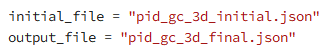
      One option is to create a .json file corresponding to your desired initial parameters, and specify that file as the initial file here. 

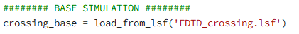
      Alternatively, some of our other lumopt examples load the initial conditions from an existing .fsp or setup script. For example, in Inverse design of waveguide crossing – Ansys Optics, crossing_opt_3D.py loads the initial simulation from lsf script:

      I think that you could similarly load a base simulation for the grating coupler. I will note, however, that the optimizable geometry typically needs to be defined separately as a FunctionDefinedPolygon with parameters that are optimized. So the base simulation setup is only for the input/output waveguides, mesh override region, and FOM monitors, while the optimizable geometry is constructed from a Python script using supplied initial parameters. So in either case, the optimizable geometry needs to be defined by parameters (numbers) that are optimized. 

      I hope this helps. 


      Best,

      Anna

    • rahul.sanghvi
      Subscriber

      Hi Anna, 
      In 2D inverse design grating coupler, the grating position are defined by 50 points/cordinates. This result is used in 3D inverse design grating coupler but it has now 51 points/cordinates. Can you explain how is there one additional cordinate ?

      Please refer to files: 
      2D inverse design grating coupler: pid_optim_final.json
      3D inverse design grating coupler: pid_gc_2d_initial.json

    • rahul.sanghvi
      Subscriber

      Hello, 

      I modified the Inverse design of grating coupler (2D) according to my purpose, everything worked as expected. But in the last step "pid_grating_coupler_2D_1etch.py" my optimisation gets stuck after the first simulation. 

      I tried changing the bounds, pgtol, and the step size, but it still does not work. 

      Can you point out what could be wrong here ?

      Thanks in advance!

    • anna.wirth-singh
      Ansys Employee

      Hi Rahul,

      Apologies for the delayed reply - I was on business travel. 

      Often, the reason that an optimization gets stuck is the optimizable geometry wanders outside the simulation region or outside the mesh override. Can you please check that the mesh override is covering the entire structure?

      Best,

      Anna

Viewing 15 reply threads
  • You must be logged in to reply to this topic.