-
-
November 25, 2024 at 10:17 am
kubatycjan
SubscriberHello everyone,
I have slightly issue with my project for my Engineering Thesis. I wanted to make a structural analysis for my self-made car jack during which I would lift it up on 3 chosen heights and determine how Force of 2 Tons works on my object. All the components I made in Autodesk Inventor and assembled them in Spaceclaim. Howoever the worst part came when I opened Workbench. Cause I have no idea which parts I should combine with which joint or contact. I used Bonded to combine arms with upper base and lower base and to combine arms with upper bases I used Joints Revolute.
Size element for entire body except arms = Default (11,739 mm)
Size elements of arms = 1,2 mm
Entire construction is made of Structural Steel
After entire analysis I get 3 warnings:
1) One or more MPC or Lagrange Multiplier formulation based contact regions or remote boundary conditions may have conflicts with other applied boundary conditions or other contact or symmetry regions. This may reduce solution accuracy. For MPC based remote points, setting the relaxation method may help eliminate overconstraint. Tip: You may graphically display FE Connections from the Solution Information Object for non-cyclic analysis. Refer to Troubleshooting in the Help System for more details.
2) Joints are being used in the current analysis with Large Deflection turned Off. Thus, only linearized joint behavior will be considered. If finite rotation and large deflection effects are to be considered, please turn on Large Deflection.
3) Two or more remote boundary conditions are sharing a common face, edge, or vertex. This behavior can cause solver overconstraint and is not recommended, please check results carefully. You may select the offending object and/or geometry via RMB on this warning in the Messages window.
What should I do in this situation to fix it and make it work ? What kind of joints or contacts should I choose for which part of car jack ?
PS: There is no intervention beetween parts and the clearance is ok.
-
November 25, 2024 at 12:33 pm
josh dudman
SubscriberHi,
I can't see exactly where you've applied your joints/contacts so you may not be doing too much wrong already but do you not need 16 revolute joints in total, one at each end of each arm?
You could delete all of the contacts and apply fixed joints between the screw and the two parts it feeds through.
With a fixed boundary condition on the bottom face of the jack base that should then be stable but not over constrained.
'Joints are being used with large deflection turned off' I believe is an automatic message when using joints and in this case can be ignored as long as deformations look sensible in the results.
Regards, Josh
-
November 25, 2024 at 1:19 pm
kubatycjan
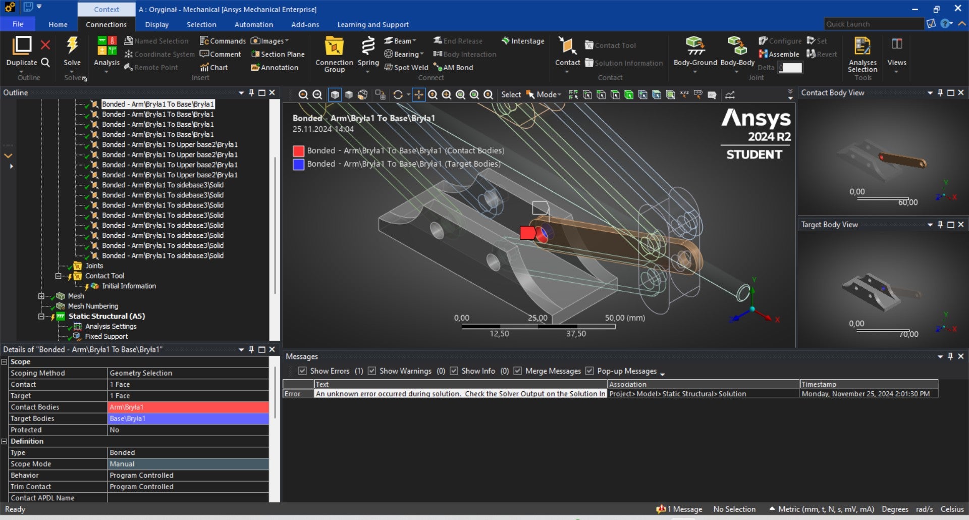
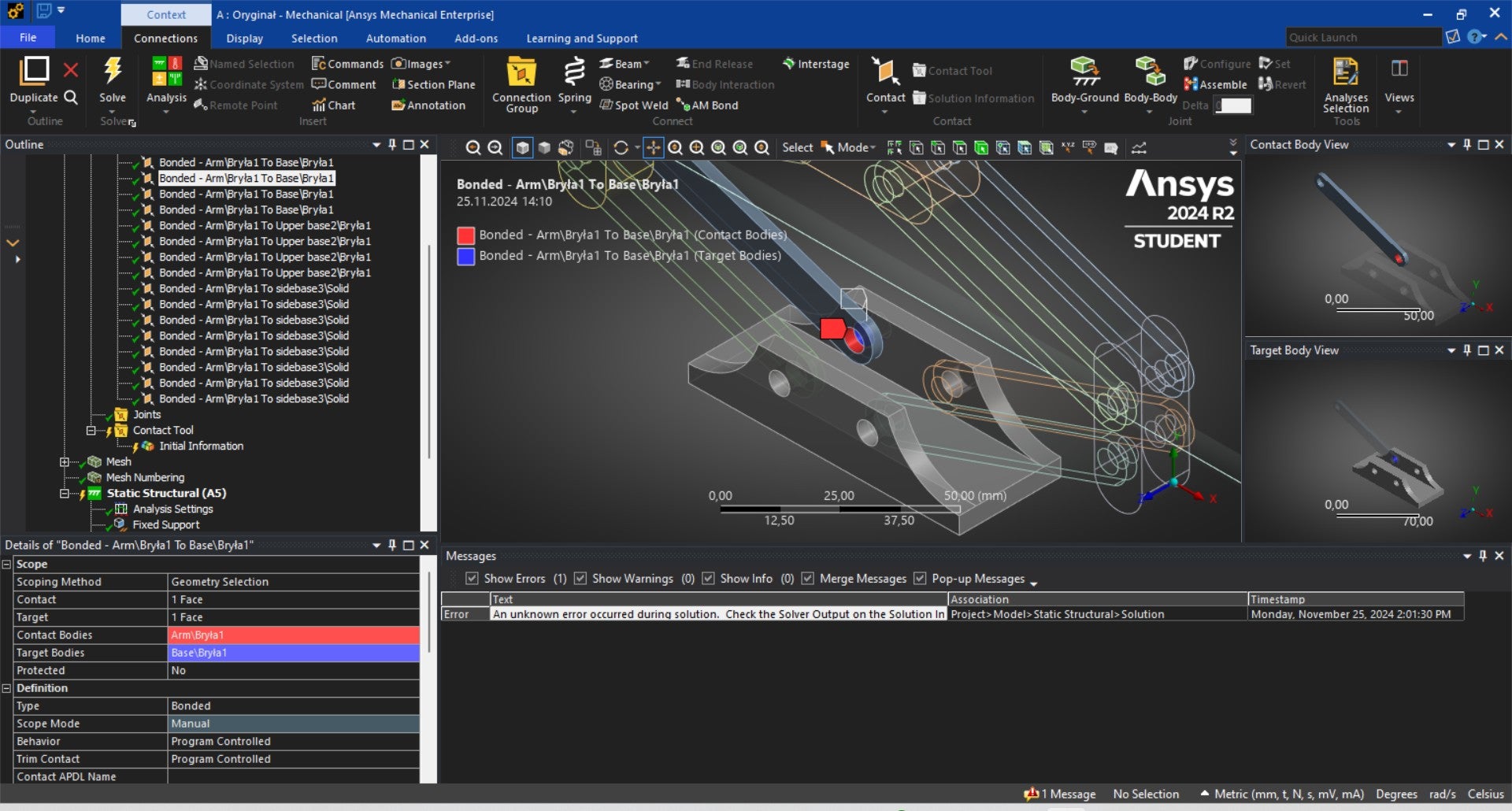
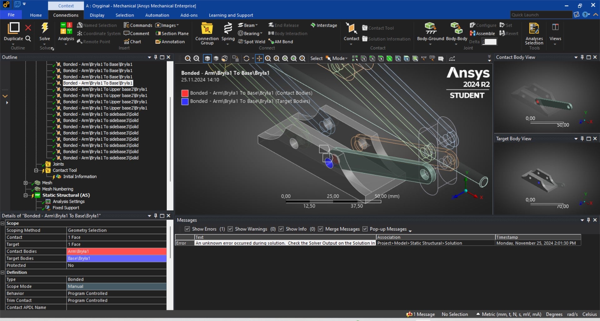
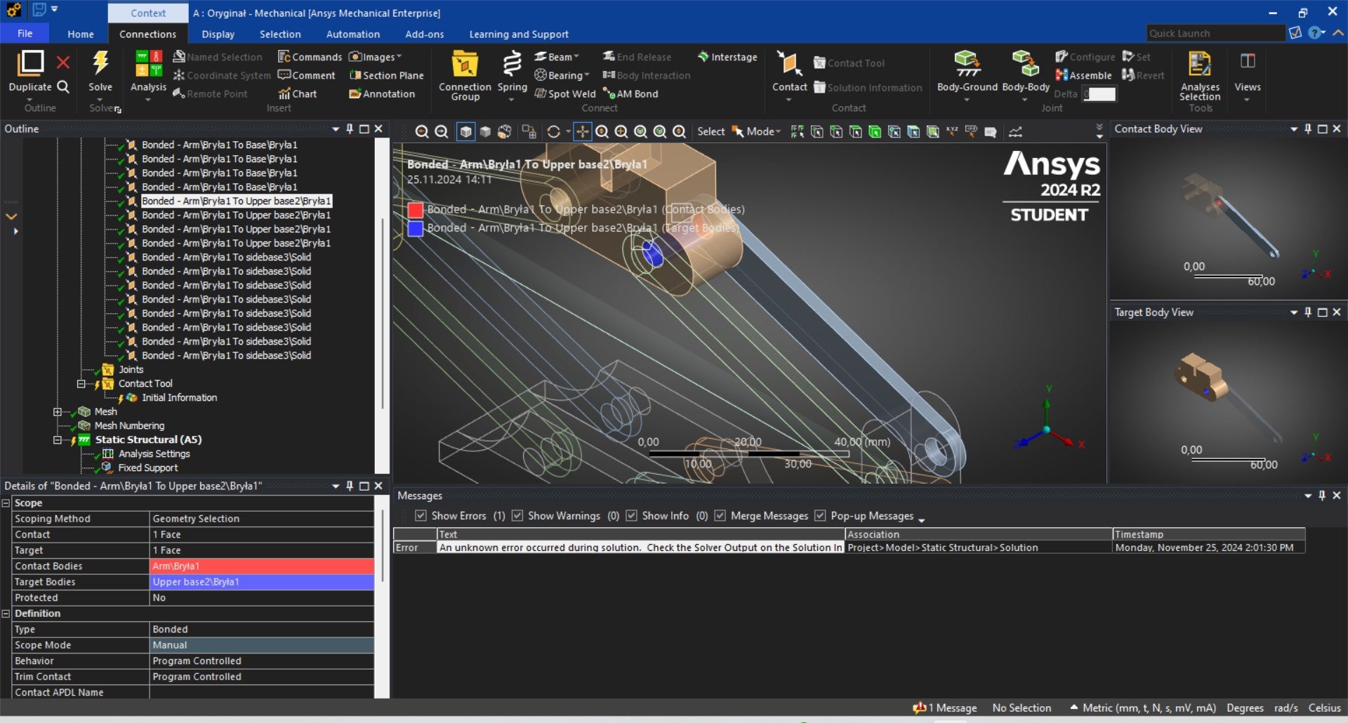
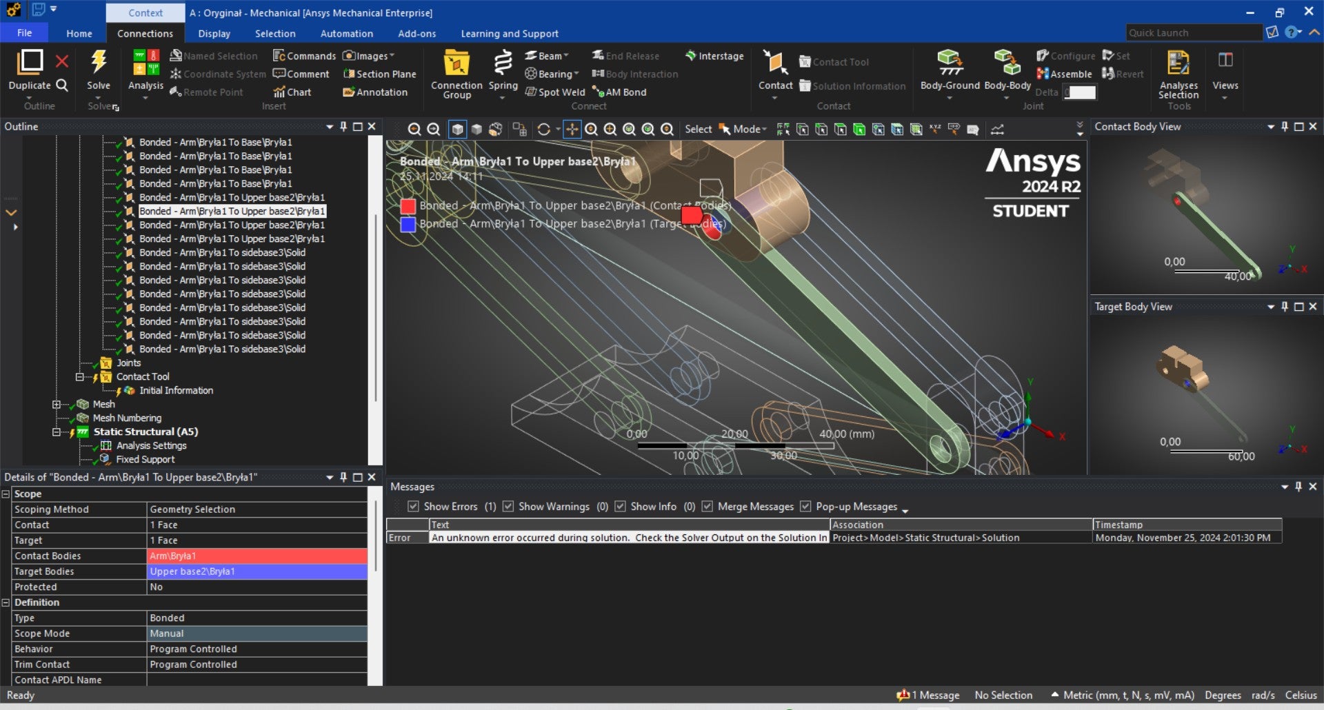
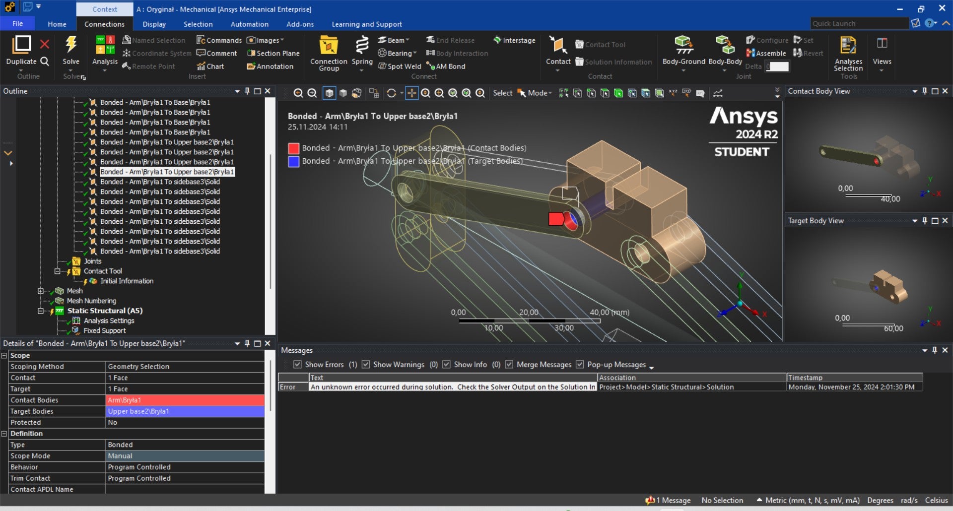
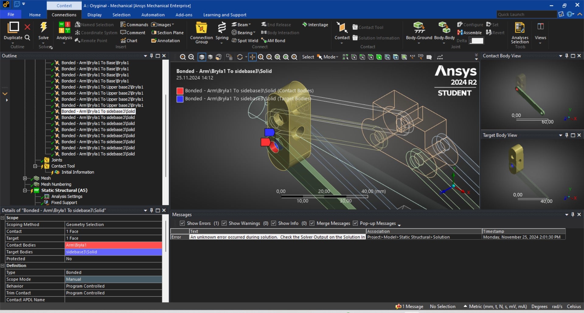
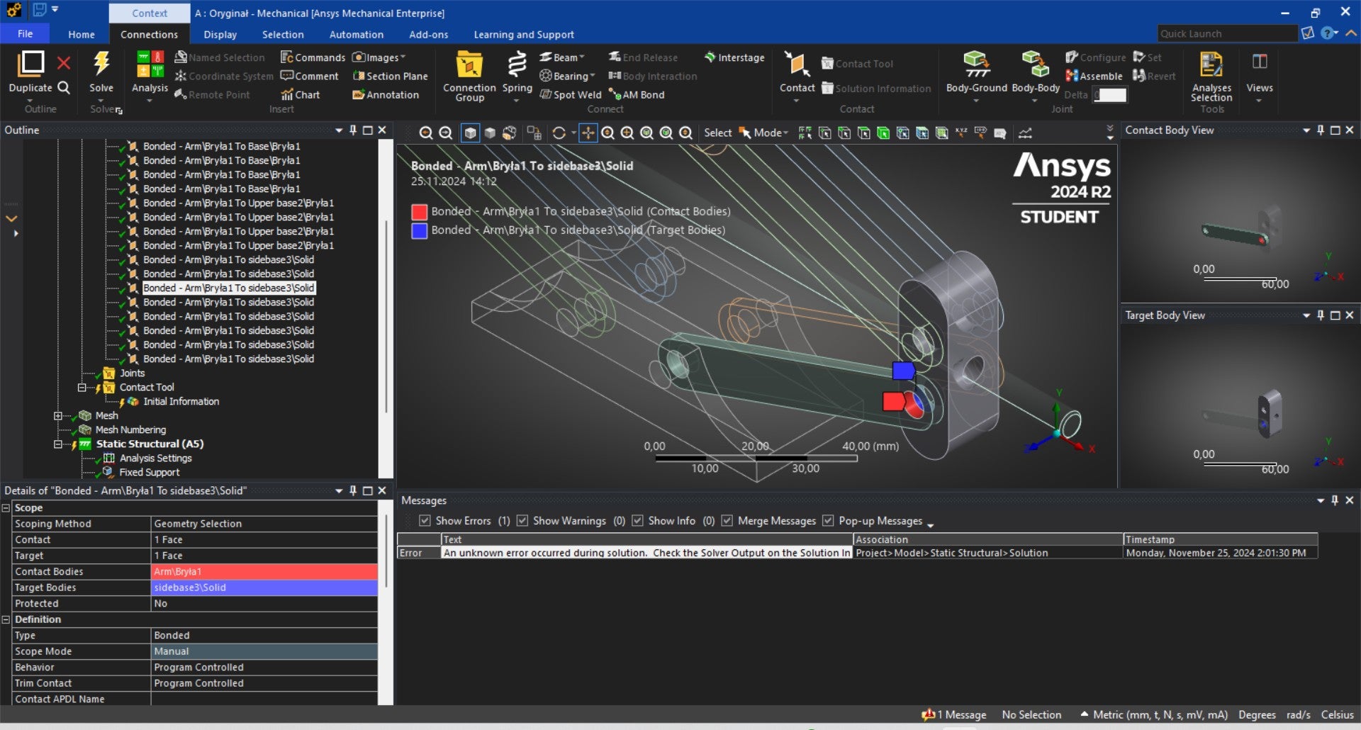
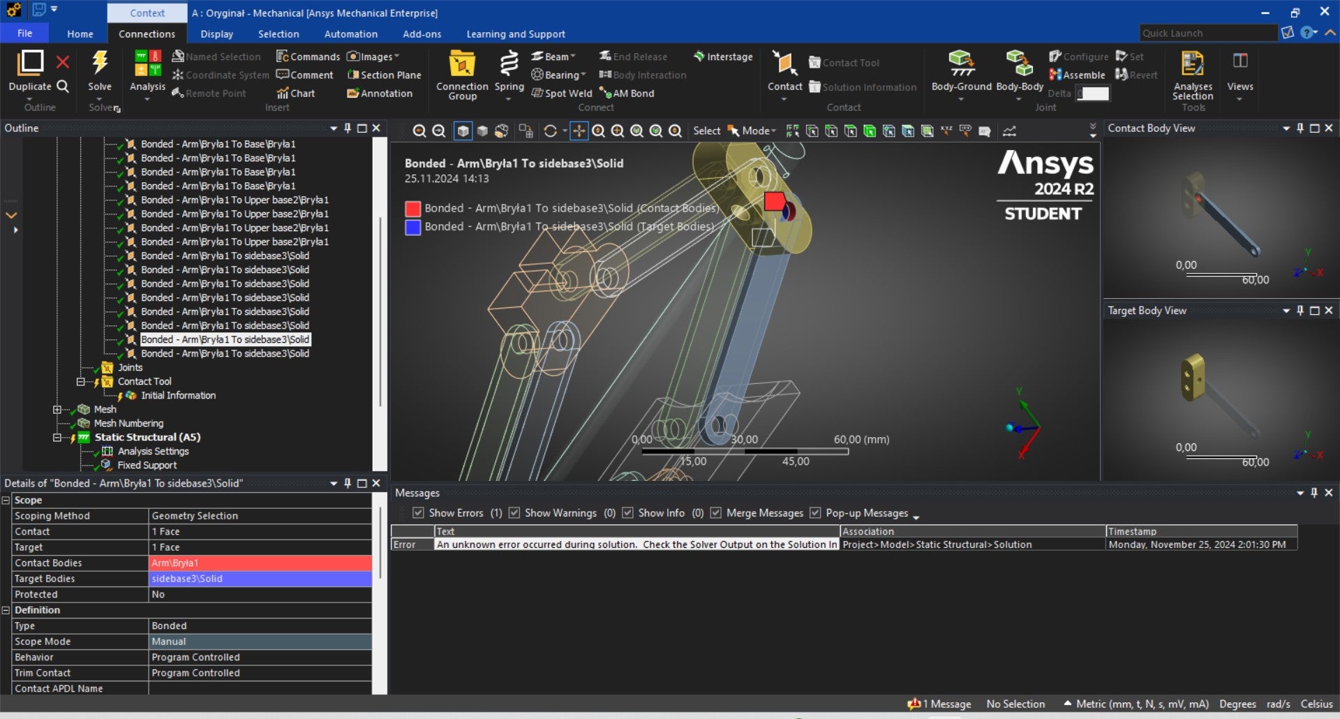
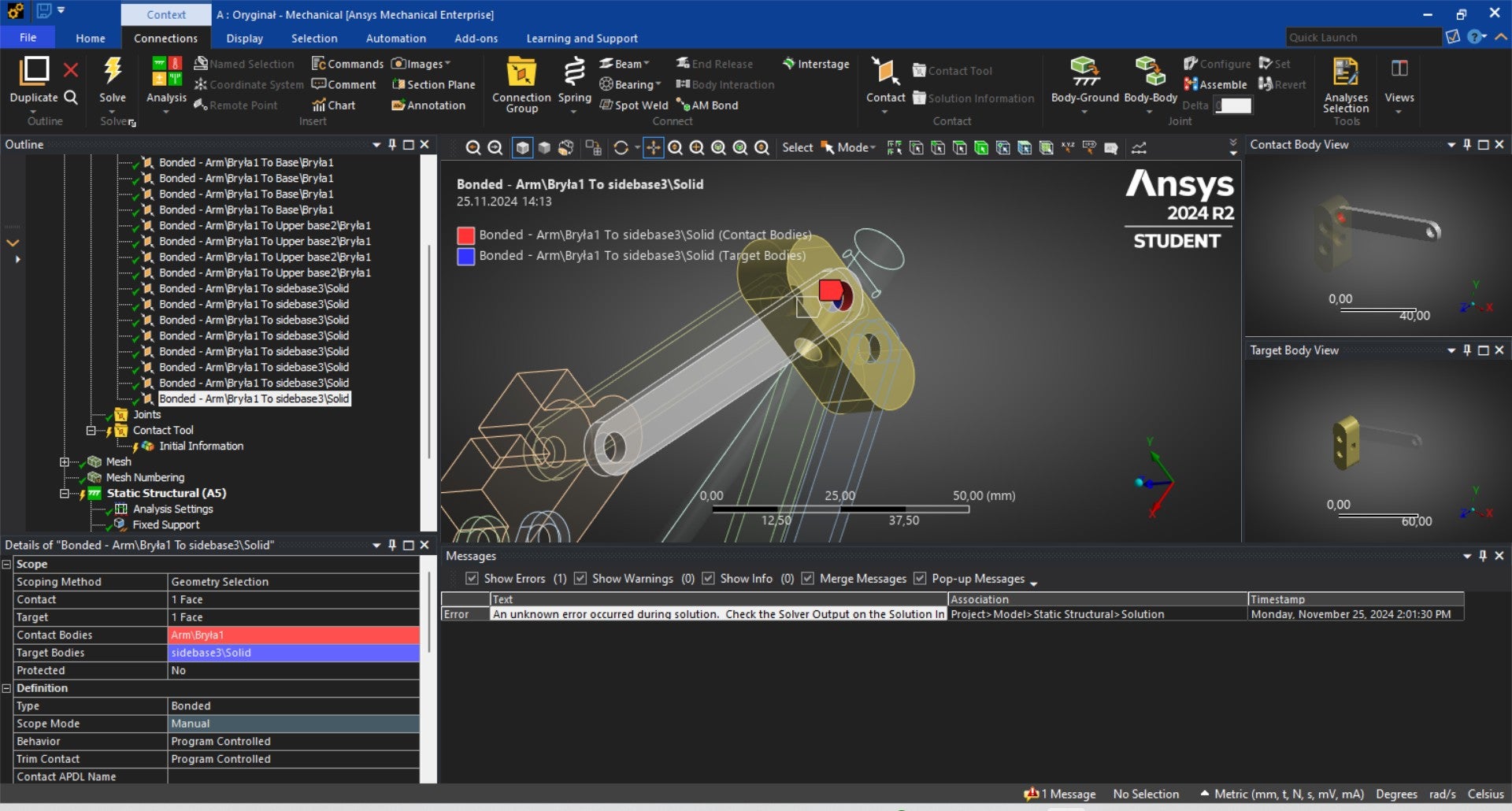
SubscriberHi John, thank you very much for your response. Meanwhile before I read your message I made some changes and instead of using joints I used contact Bonded cause in my situation my car jack is under the car and it's lifted on certain height. During my analysis the message showed up:
An unknown error occurred during solution. Check the Solver Output on the Solution Information object for possible causes.
Speakig of Joints You said that I don't need use all 16 joints. So which joints and where shoud I place them to make it work ?
Regards, Jacob
-
-
November 25, 2024 at 2:40 pm
josh dudman
SubscriberI don't think bonded contacts would be the best option here as you don't have face to face contact between the parts.
If you use the same contact and target faces for each pivot location but instead with revolute joints I believe it should work.
Also have you applied a fixed joint between the screw and the two components it passes through?
Regards, Josh
-
November 25, 2024 at 5:28 pm
kubatycjan
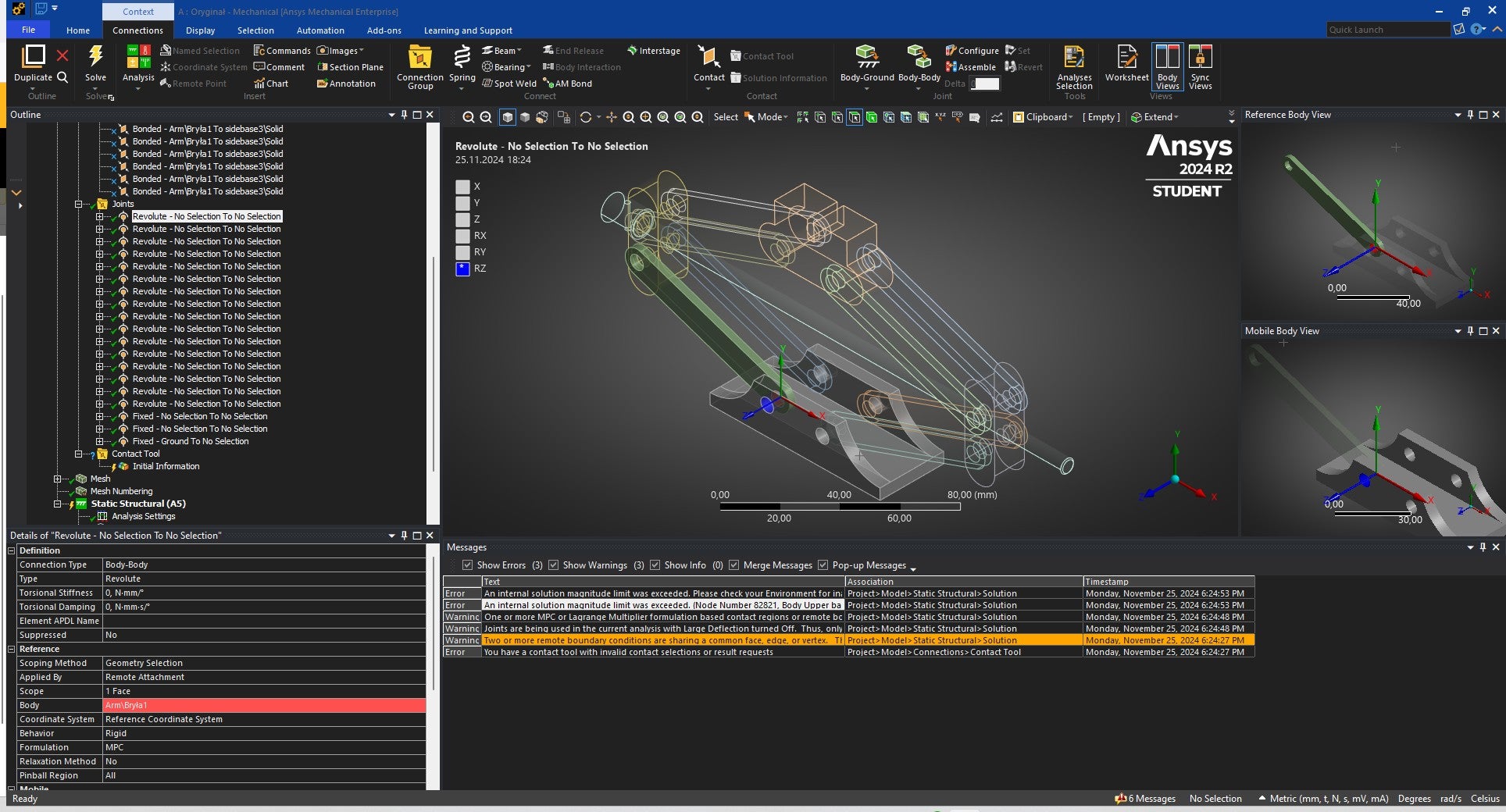
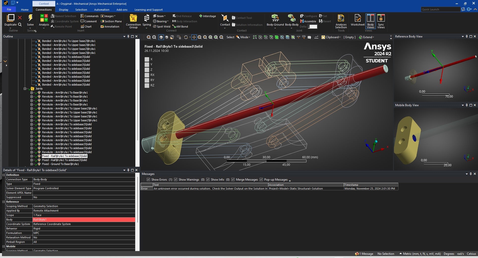
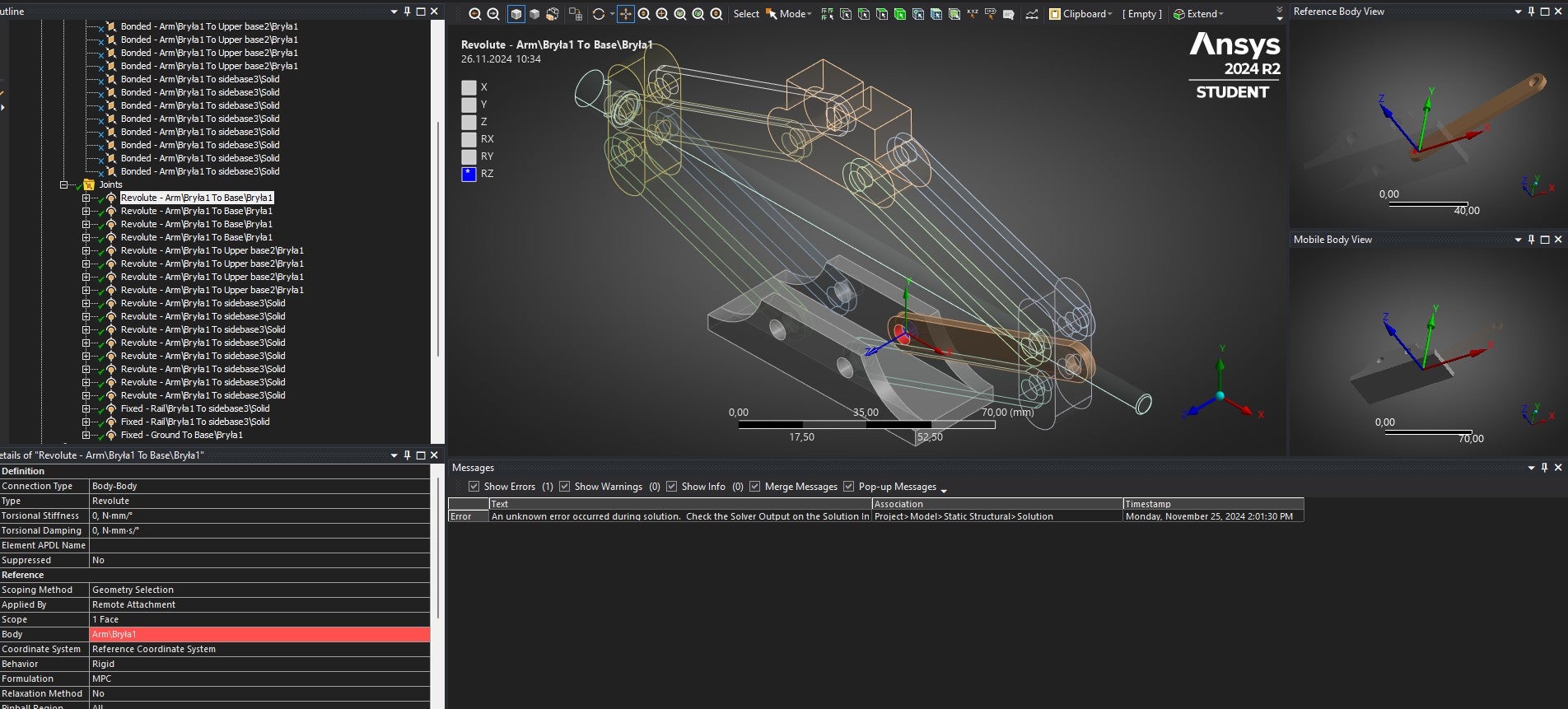
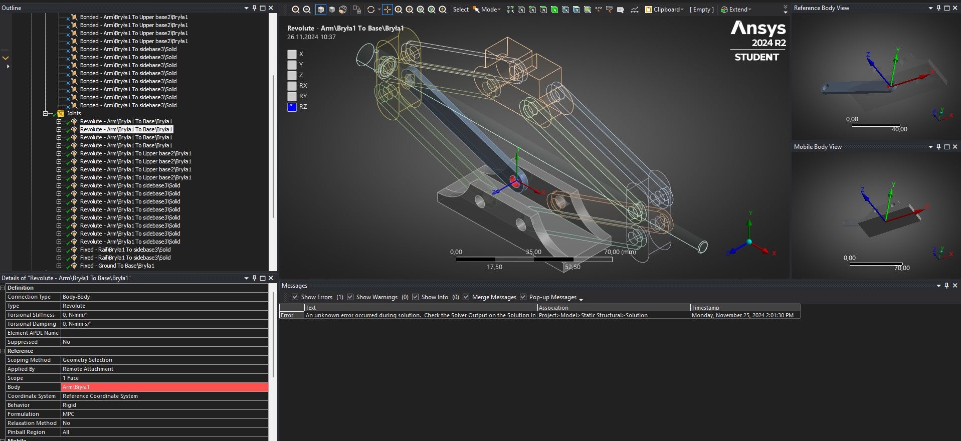
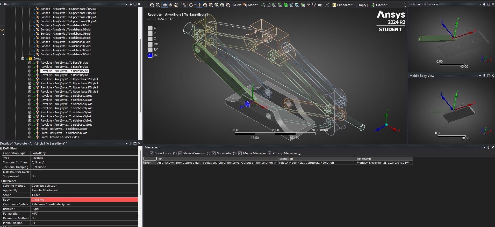
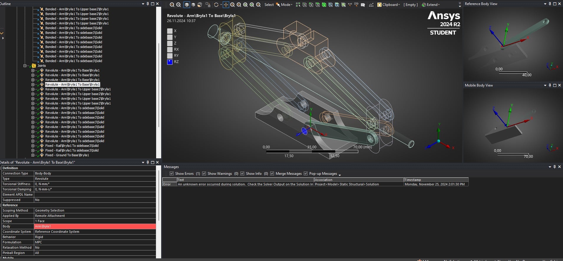
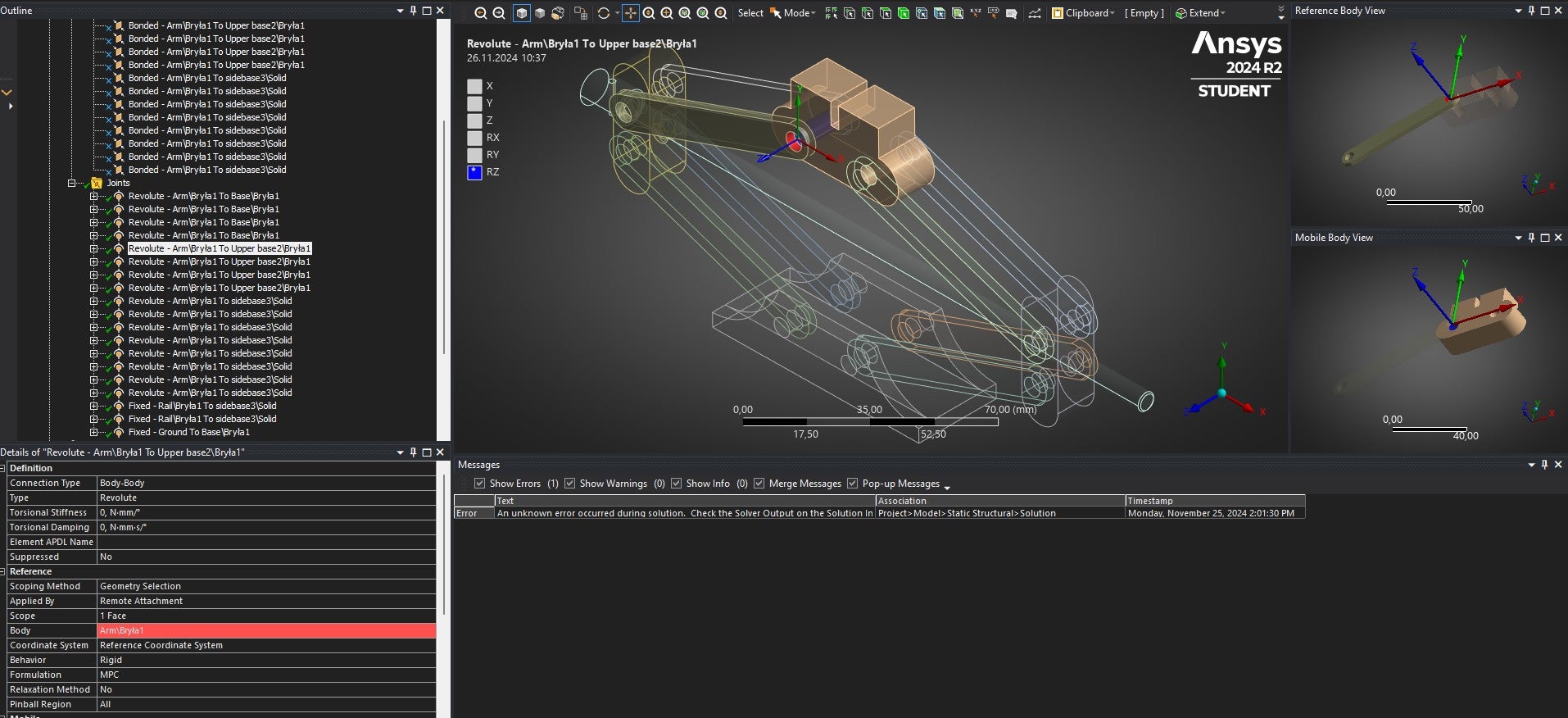
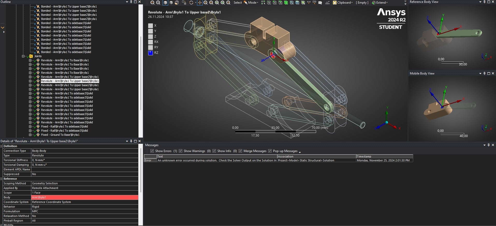
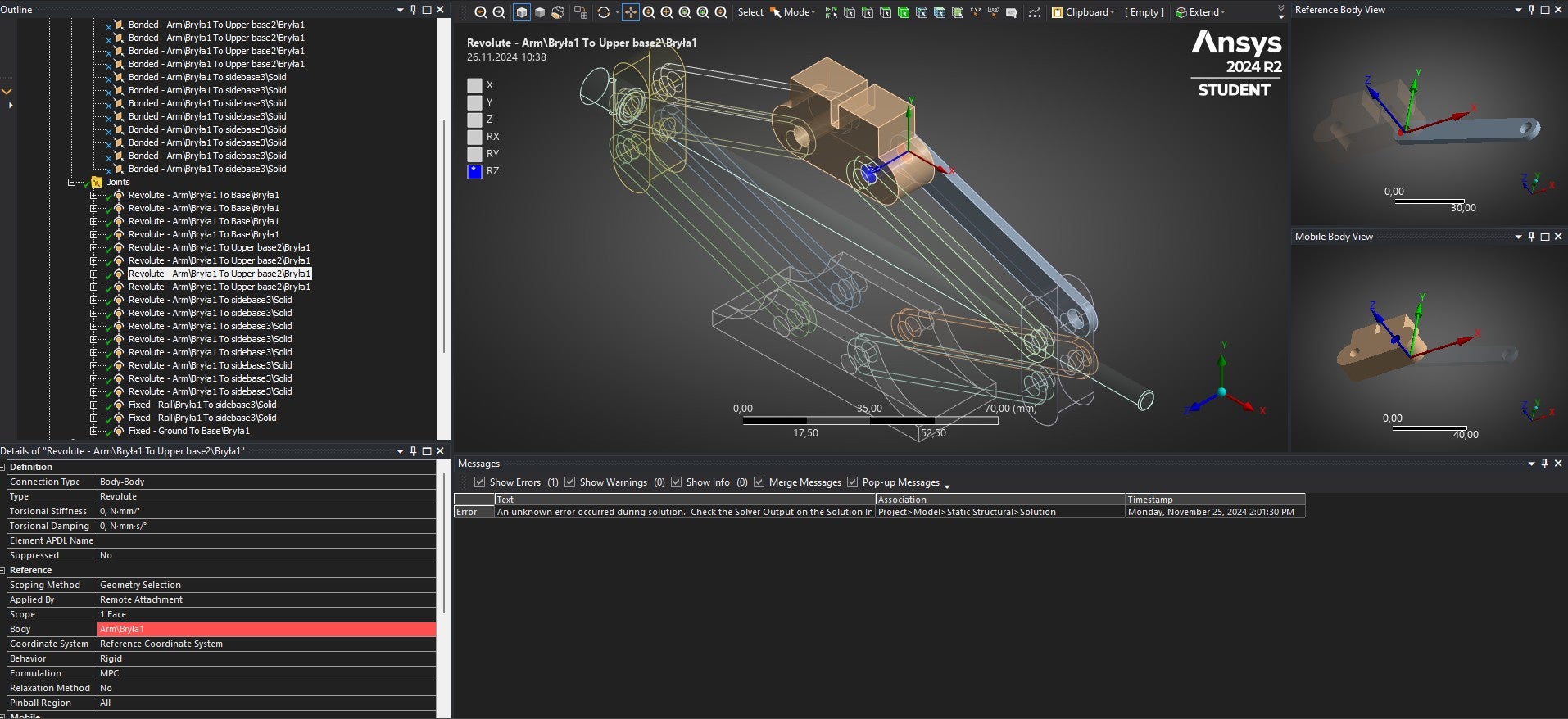
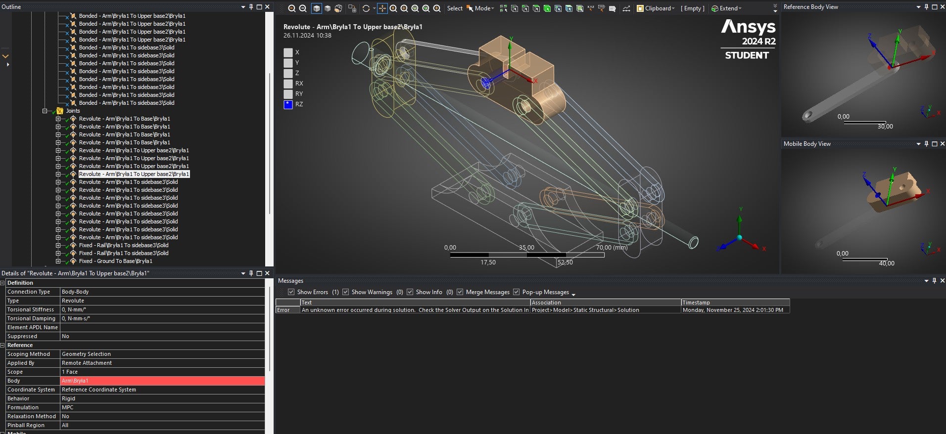
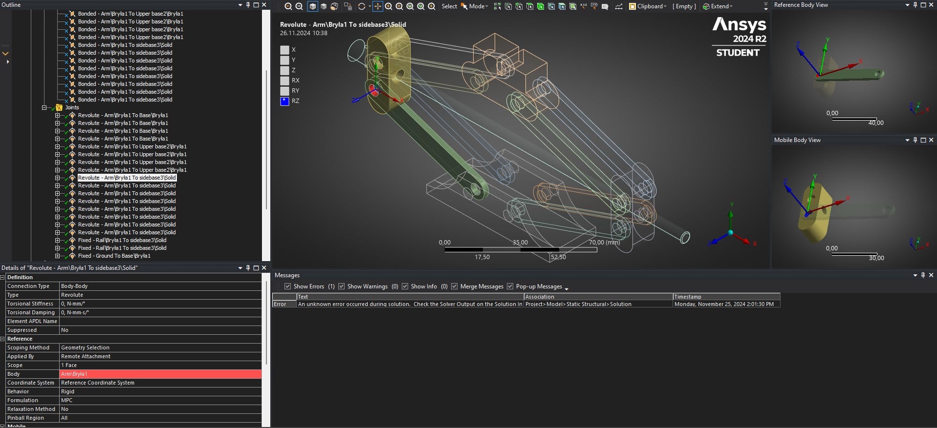
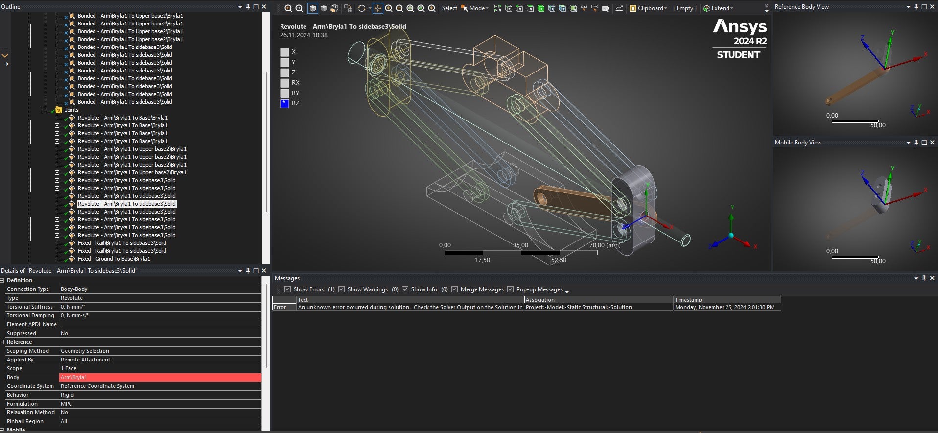
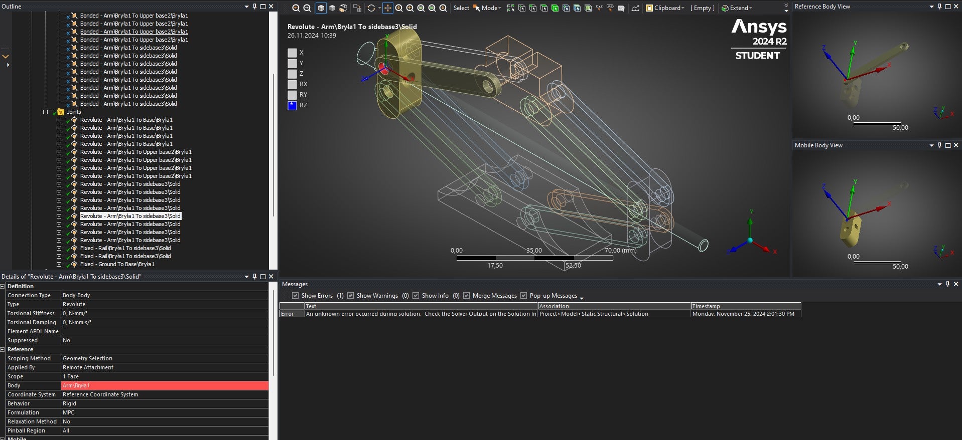
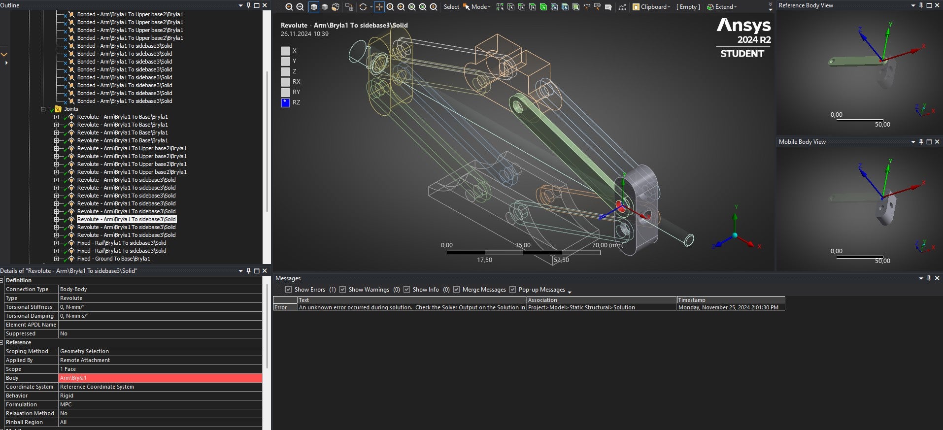
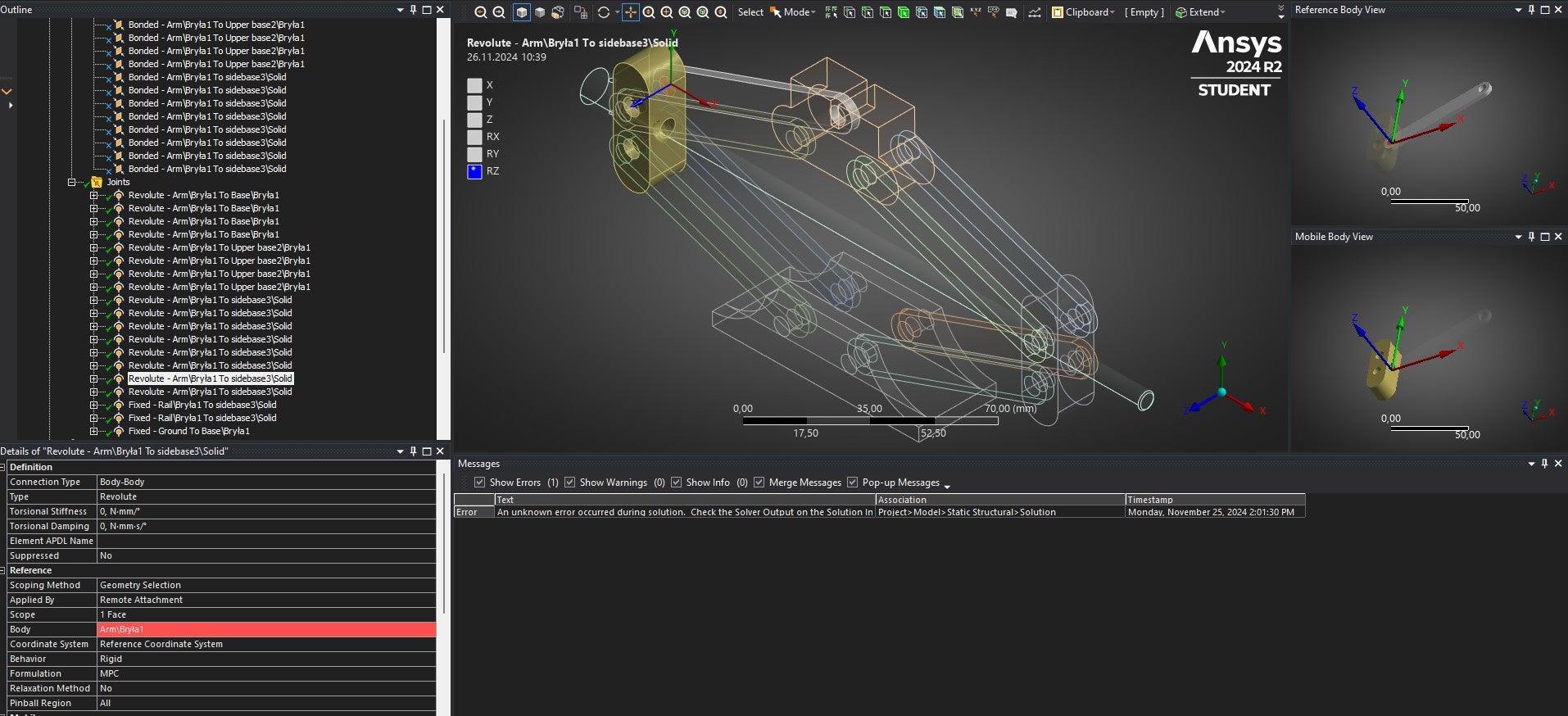
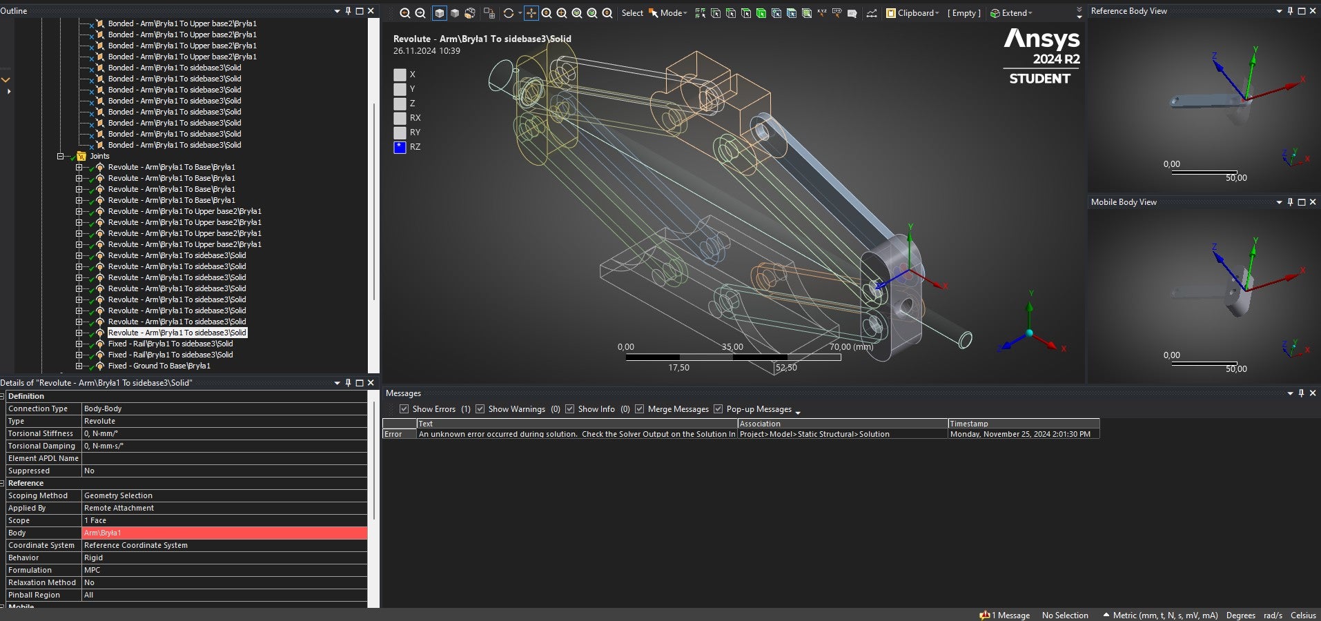
SubscriberI surpressed all bonded contacts and used joints revolute instead, and also I applied a fixed joint between the screw and the two components it passes through.
What’s more I applied joint body-ground for the floor of my car.
But then 3 Warnings showed up :
1)One or more MPC or Lagrange Multiplier formulation based contact regions or remote boundary conditions may have conflicts with other applied boundary conditions or other contact or symmetry regions. This may reduce solution accuracy. For MPC based remote points, setting the relaxation method may help eliminate overconstraint. Tip: You may graphically display FE Connections from the Solution Information Object for non-cyclic analysis. Refer to Troubleshooting in the Help System for more details.
2) Joints are being used in the current analysis with Large Deflection turned Off. Thus, only linearized joint behavior will be considered. If finite rotation and large deflection effects are to be considered, please turn on Large Deflection.
3) Two or more remote boundary conditions are sharing a common face, edge, or vertex.This behavior can cause solver overconstraint and is not recommended, please check results carefully. You may select the offending object and/or geometry via RMB on this warning in the Messages window.
Error: An internal solution magnitude limit was exceeded. (Node Number 82821, Body Upper base2\Bryła1, DOF UY) Please check your Environment for inappropriate load values or insufficient supports. You may select the offending object and/or geometry via RMB on this warning in the Messages window. Please see the Troubleshooting section of the Help System for more information.
-
-
November 25, 2024 at 6:01 pm
josh dudman
SubscriberThe error message suggests there is a large change in position of one or more of the parts.
Your revolute joint is looking good. If all of them are applied in the same way and your fixed joints are applied correctly I don't see why a large deflection would occurr.
How have you applied the fixed joints between the screw and the two components it passes through? And where did you apply the fixed body-ground joint on the base?
Regards, Josh
-
November 26, 2024 at 9:33 am
-
November 26, 2024 at 9:45 am
-
November 26, 2024 at 9:51 am
-
November 26, 2024 at 5:48 pm
kubatycjan
Subscriber
-
-
November 26, 2024 at 10:38 am
josh dudman
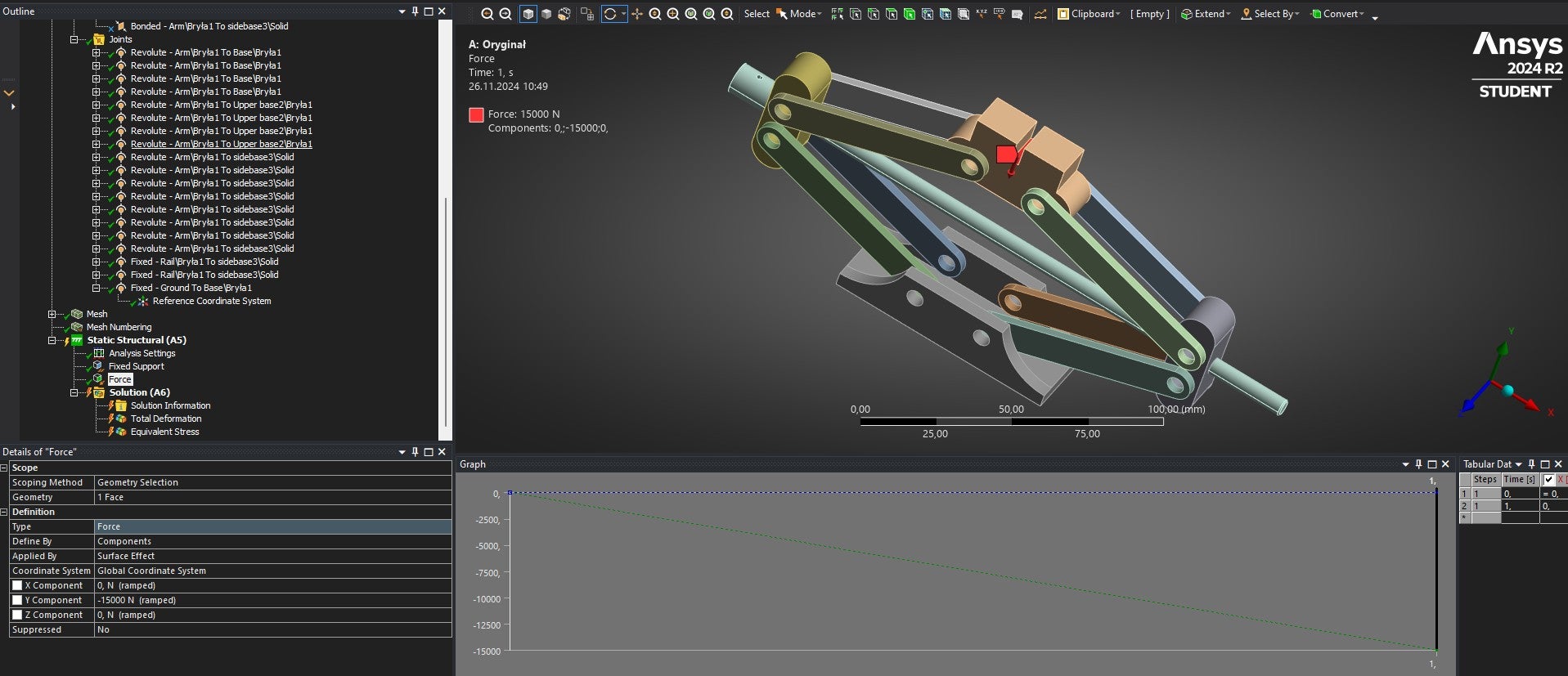
SubscriberYou've applied the fixed boundary condition twice, once with the joint and once witht the support, which is producing an over constraint.
Remove one or the other and it should work.
Regards, Josh
-
November 26, 2024 at 2:34 pm
kubatycjan
SubscriberNew warnings and errors showed up:
Error: An internal solution magnitude limit was exceeded. Please check your Environment for inappropriate load values or insufficient supports. Please see the Troubleshooting section of the Help System for more information.
Error: An internal solution magnitude limit was exceeded. (Node Number 82894, Body Rail\Bryła1, DOF UY) Please check your Environment for inappropriate load values or insufficient supports. You may select the offending object and/or geometry via RMB on this warning in the Messages window. Please see the Troubleshooting section of the Help System for more information.
Warning 1 : Joints are being used in the current analysis with Large Deflection turned Off. Thus, only linearized joint behavior will be considered. If finite rotation and large deflection effects are to be considered, please turn on Large Deflection.
Warning 2:Two or more remote boundary conditions are sharing a common face, edge, or vertex. This behavior can cause solver overconstraint and is not recommended, please check results carefully. You may select the offending object and/or geometry via RMB on this warning in the Messages window.
-
November 26, 2024 at 2:35 pm
ErKo
Ansys EmployeeYou have posted in several posts and many images.
To save and not to make many and very long posts, perhaps it is more efficient if you provide a link (for model archive .wbpz) so other user (e.g., Josh or Peter Newman who are not Ansys employees - we are not allowed to download any models), can download and look at the model (sure it is something small missing).
Erik
-
November 26, 2024 at 3:09 pm
kubatycjan
SubscriberAlright, I will do it. I will share wbpz file on my google drive . I apologise for making all this fuss about it but I am really desperate to finish this for my Engineering Thesis and I slowly running out of the time
https://drive.google.com/file/d/1LmqlqdTsXEA2U70utCHf1zBxpWKKCHuZ/view?usp=sharing
-
November 26, 2024 at 3:10 pm
ErKo
Ansys EmployeeHi
Check why it is not conv.,
- by add. substeps:
https://www.youtube.com/watch?v=CDn8NyiOGr8
- and/or run a modal analysis (any rigid body modes will indicate the issue).
Also:
One thing to do to resolve this is :
- remove force
- add displacement at force location and push it down in y say by 0.0005 m (Z=X= 0 m).
- Look at the reaction at this displacement to get the force.
In this way the model should solve I hope and we can see how it behaves
All the best
Erik
-
November 26, 2024 at 5:55 pm
-
November 27, 2024 at 7:29 am
ErKo
Ansys EmployeeHi
Please do as below and follow it in detail:
- Remove the force you applied (delete the force)
- Add a displacement at the force location/face and push it down in y say by 0.0005 m (fix Z=X= 0 m).
- Look at the reaction at this displacement to get the force applied due to displacement. To do that : Drag and drop the applied displacement to the solution/results in the tree (see here:
The displacement is needed since the model might not be stable (run a modal analysis and look for modes with freq.~ 0 Hz which are rigid body modes and show any instability).
-
November 27, 2024 at 9:37 am
-
November 27, 2024 at 9:43 am
ErKo
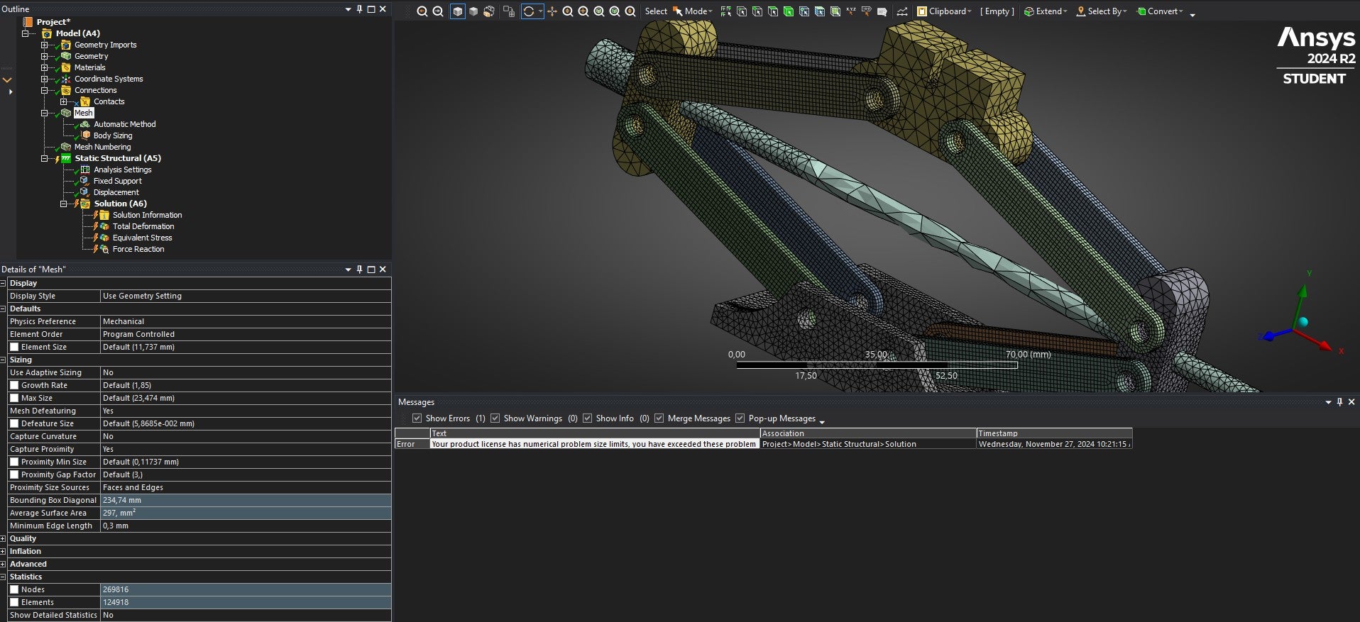
Ansys EmployeeClear the mesh generated (right mouse button click on Mesh, and clear), reduce the mesh count, so say by increassing your mesh size to double or tripple (so say 2 or 3 mm size).
Look on mesh courses also:
https://innovationspace.ansys.com/product/advanced-topics-in-ansys-mechanical-meshing/
All the best
Erik
-
-
-
November 27, 2024 at 12:18 pm
josh dudman
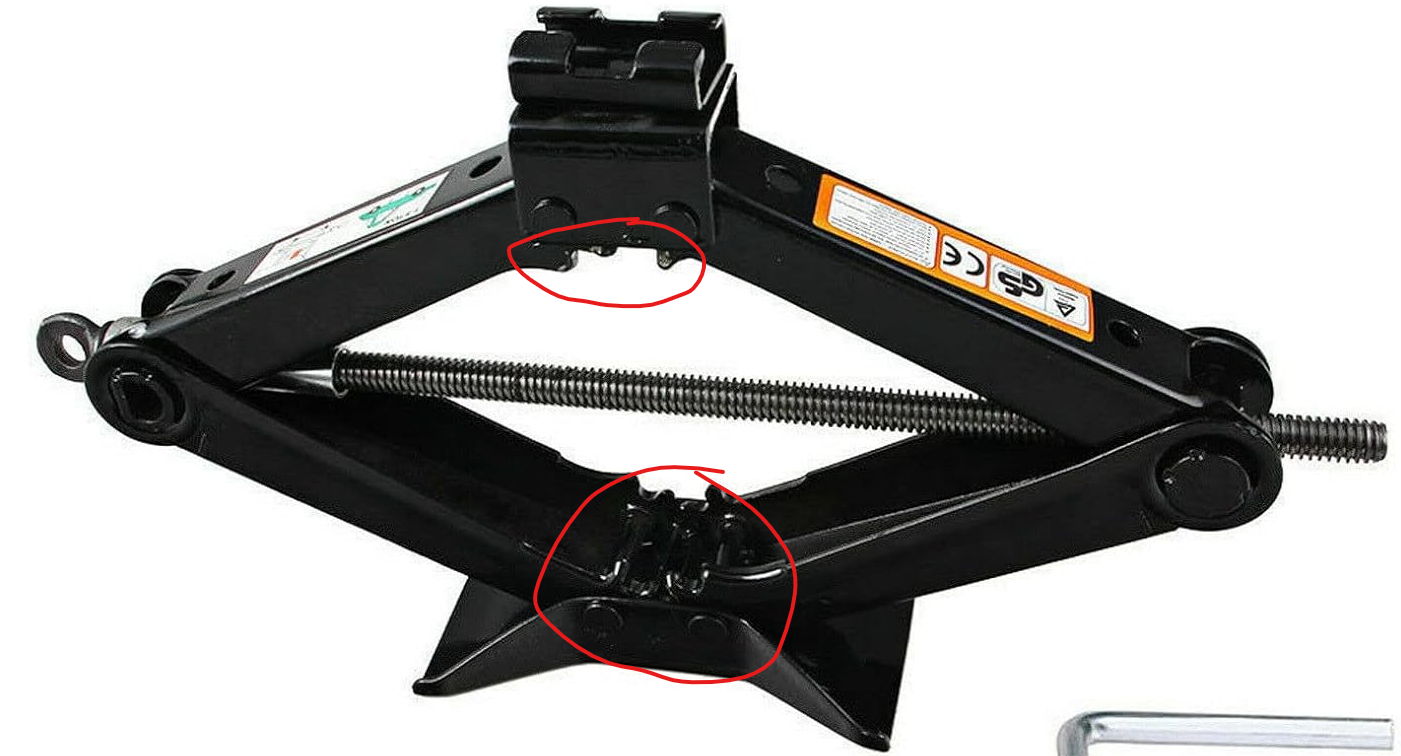
SubscriberI realised why the simulation is failing. The model is currently made up of two 4 link mechanisms on top of each other which both possess a degree of freedom. If you look at a scissor jack they actually have a cogged mechanism between the opposing arms at the base and top, see image below. When constrained in this way the arms resist a moment and the mechanism becomes fully constrained.
So in the simulation the joints between the arms and the base and top components can be fixed rather than revolute to represent this. See the updated FEA below.
https://drive.google.com/file/d/1chuUW8vorhzuTkgOcNseRWOA3mqGCn_V/view?usp=drive_link
Regards, Josh
-
November 27, 2024 at 12:21 pm
ErKo
Ansys Employeethat is what I was suspecting - and hence recommend enforced displacement to get rid of the instability.
Thanks for your help here Josh.
Much appreciated.
Erik
-
-
- The topic ‘Self-made car jack – static structural analysis’ is closed to new replies.


-
5169
-
1836
-
1387
-
1249
-
1021

© 2026 Copyright ANSYS, Inc. All rights reserved.


