-
-
November 19, 2024 at 12:25 pm
sriparna.2021rce15
SubscriberI am trying to model PZT patch (10mm x 10mm x 0.3mm) bonded on a beam (700mm x 150mm x 150mm) but I am unable to perform harmonic analysis. Therefore I tried modelling only the PZT patch but then also there are warnings. Details of the PZT patch modelled are as follows:
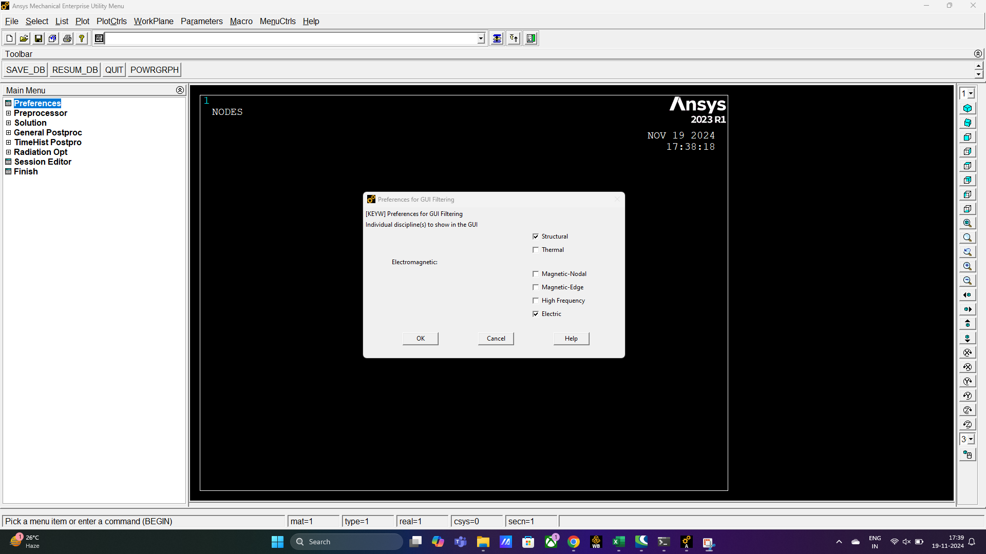
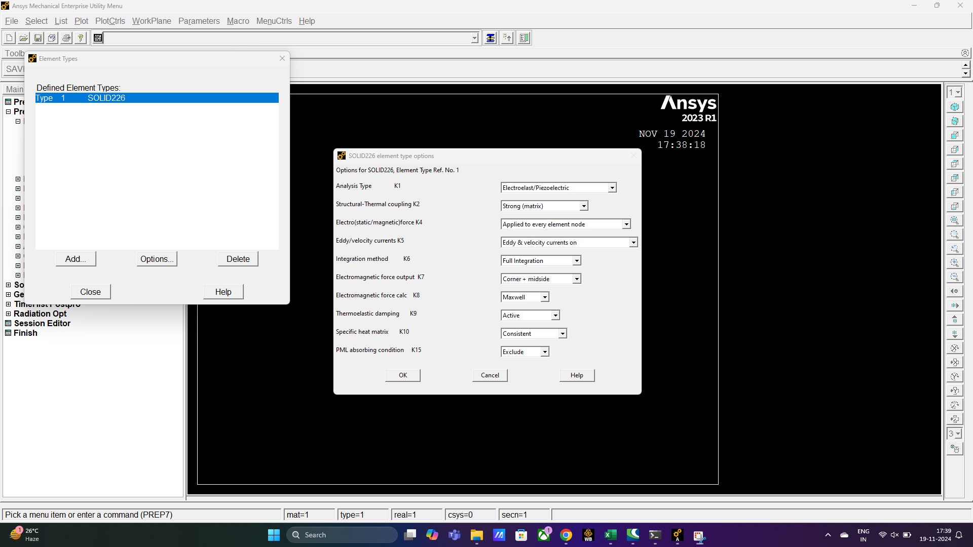
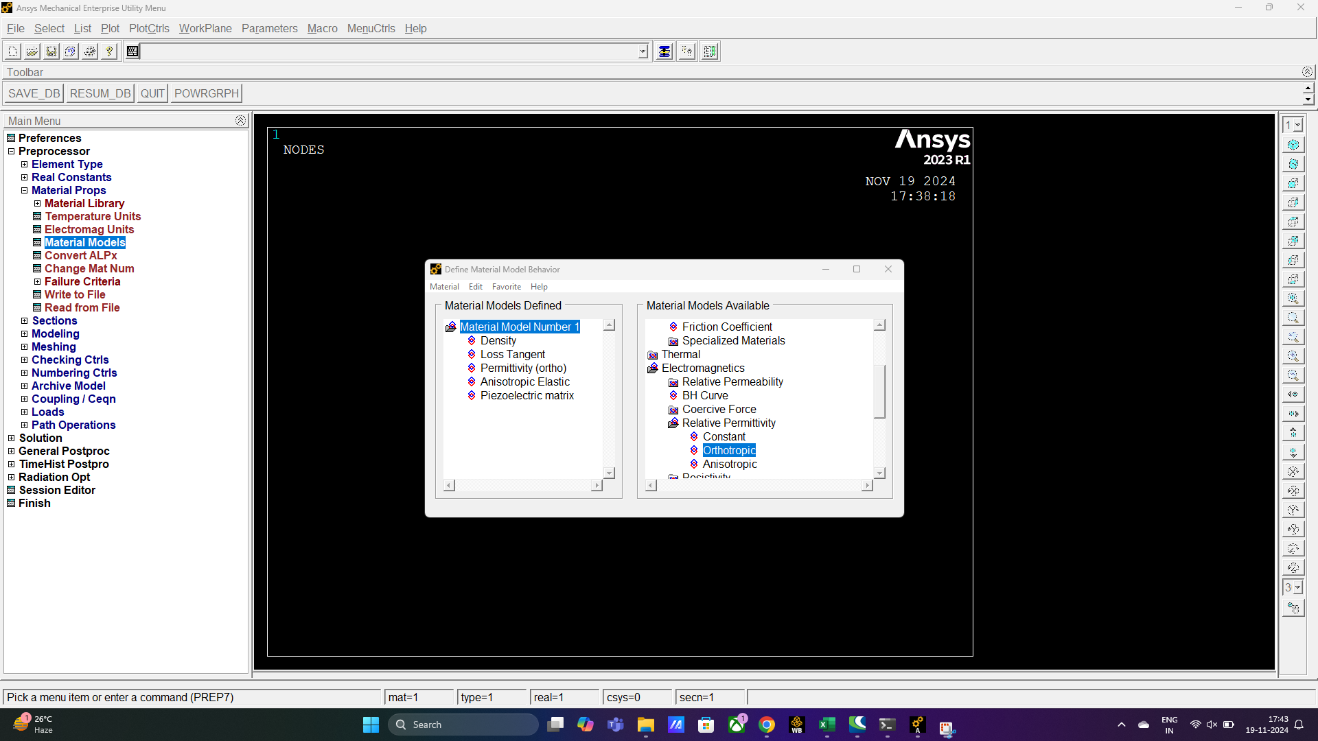
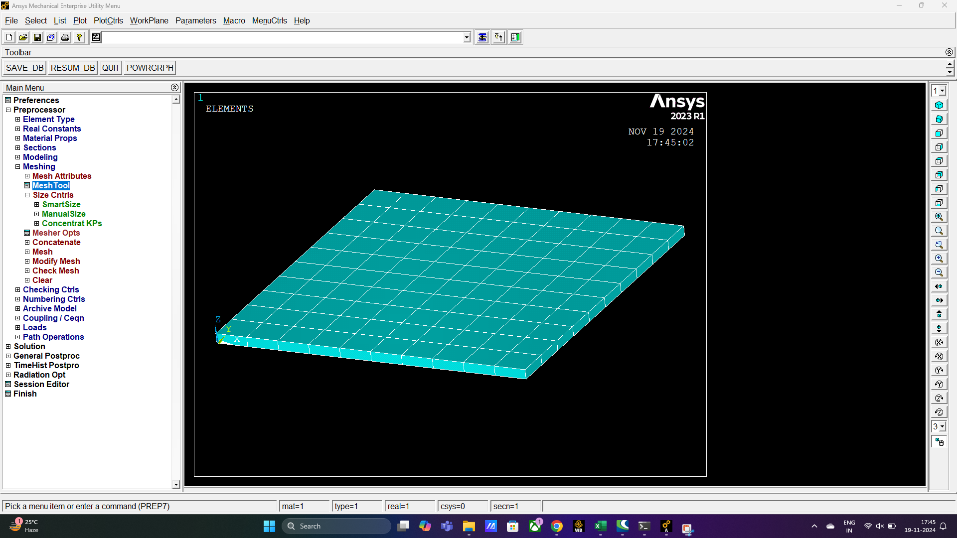
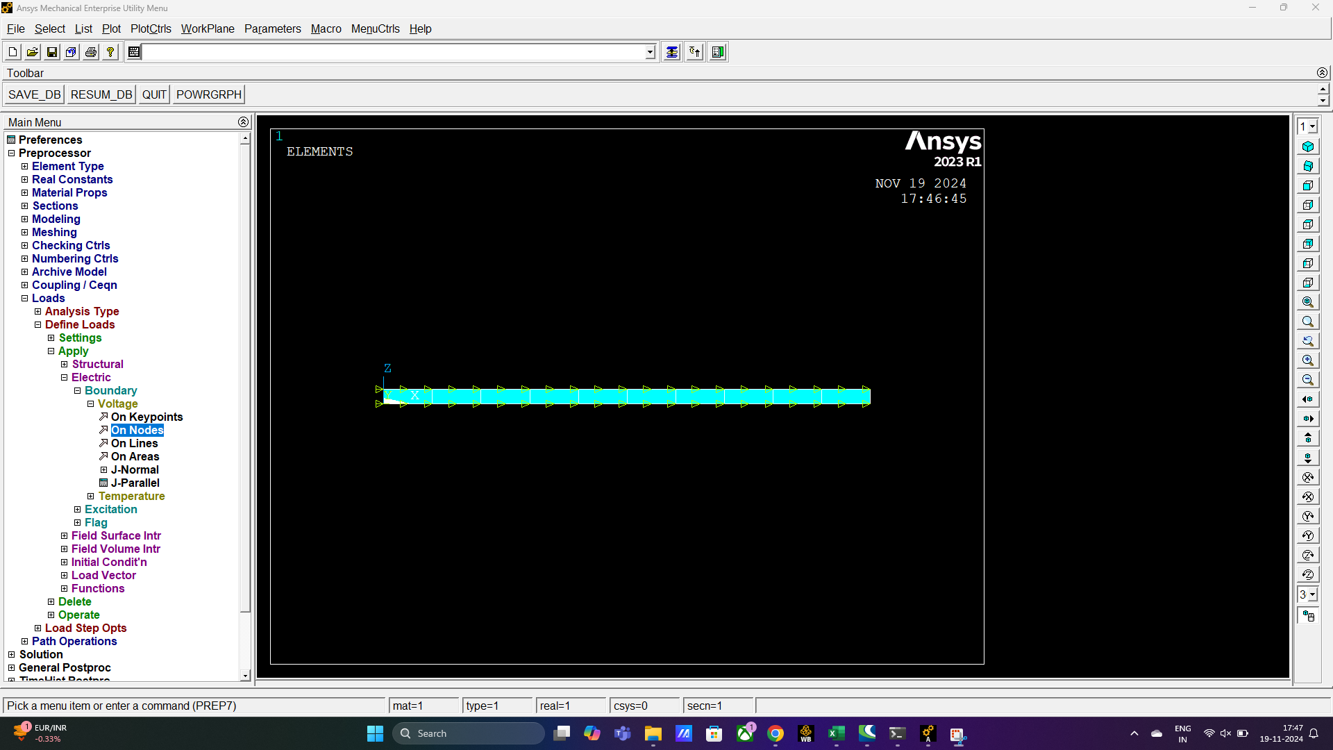
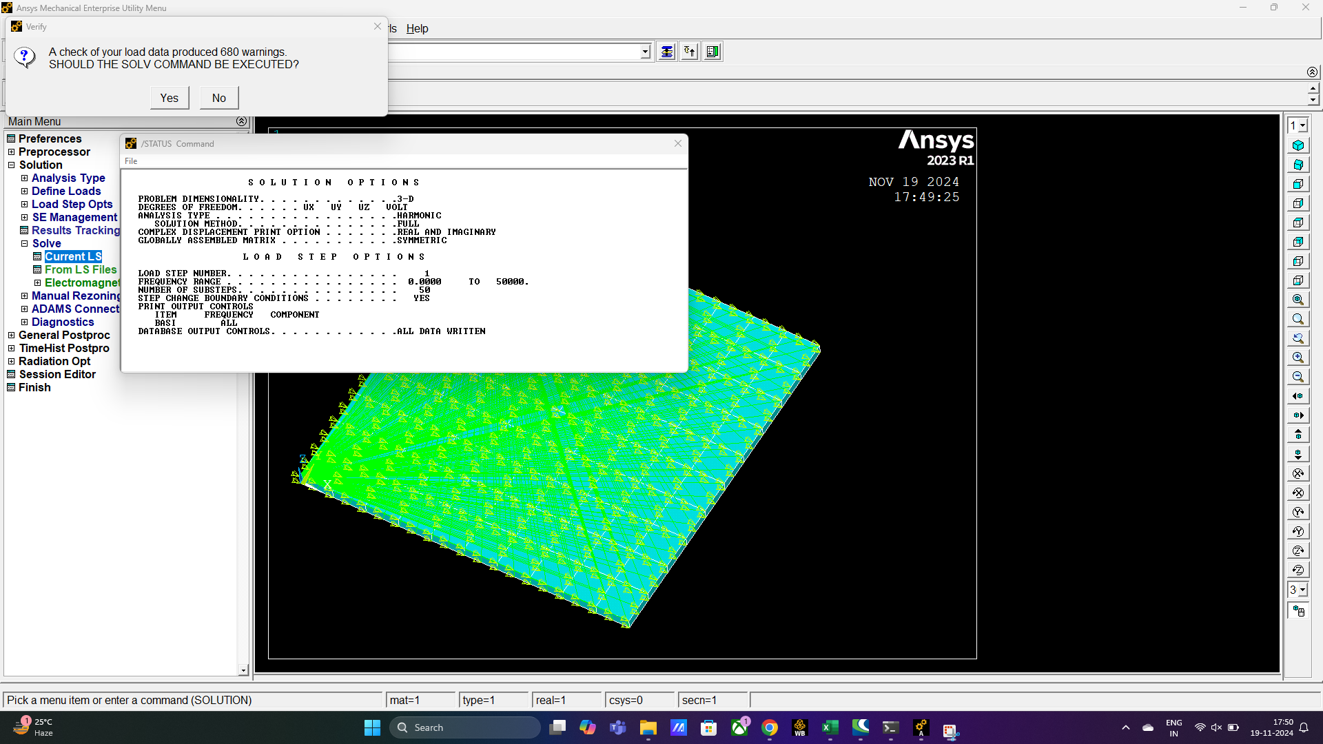
I modelled PZT-5H patch (10mm x 10mm x 0.3mm) on ANSYS APDL. The element considered for PZT-5H is SOLID226 and the k1 was set to piezoelectric. Sweep meshing was performed with the element size of 1mm. I also tried hex mapped meshing. Then I applied a voltage of 1 V at the top nodes and coupled them and applied 0V at the bottom nodes and coupled them. Then performed harmonic analysis, 680warnings were generated. Warnings stated that the node is not independent tehrefore nodes have been couple. The same error was generated for all the 680 nodes.
-
November 19, 2024 at 12:35 pm
ErKo
Ansys EmployeeHi
I would suggest to use WB mechanical and not MAPDL.
SO use the coupled field harmonic system in WB.
In help there is a tutorial:
https://ansyshelp.ansys.com/account/secured?returnurl=/Views/Secured/corp/v242/en/wb_wbtec/WBtecultratrans.html?q=Wire%20Bonding%20Ultrasonic%20Transducer
If you can not open the link above, search in the help manual for the: Mechanical Technology Showcase: Example Problems Chapter 39: Wire Bonding Ultrasonic Transducer
There is a public version of help now:
https://www.ansys.com/en-gb/blog/get-ansys-help-you-need-when-you-need-it
public version of the Ansys Help siteAll the best
Erik
-
November 21, 2024 at 5:19 am
sriparna.2021rce15
SubscriberThank you for your response sir.
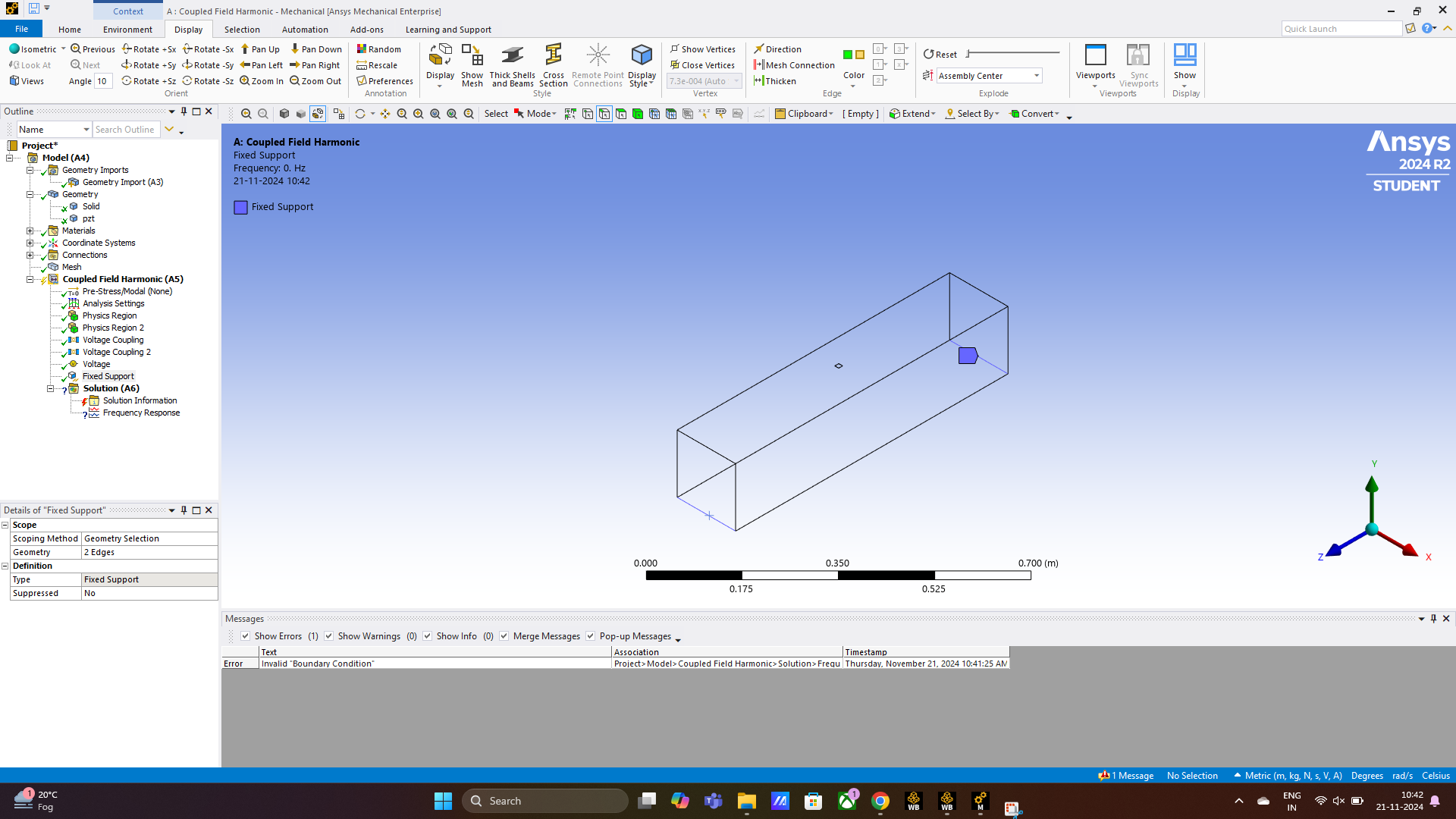
I tried performing it in workbench but I am unable to get the results. According to my understanding I developed the model and applied the voltage of 1V at the top nodes of the PZT and at the bottom node 0V. After that the nodes were coupled. But on solving I am getting an error "Invalid Boundary Conditions".
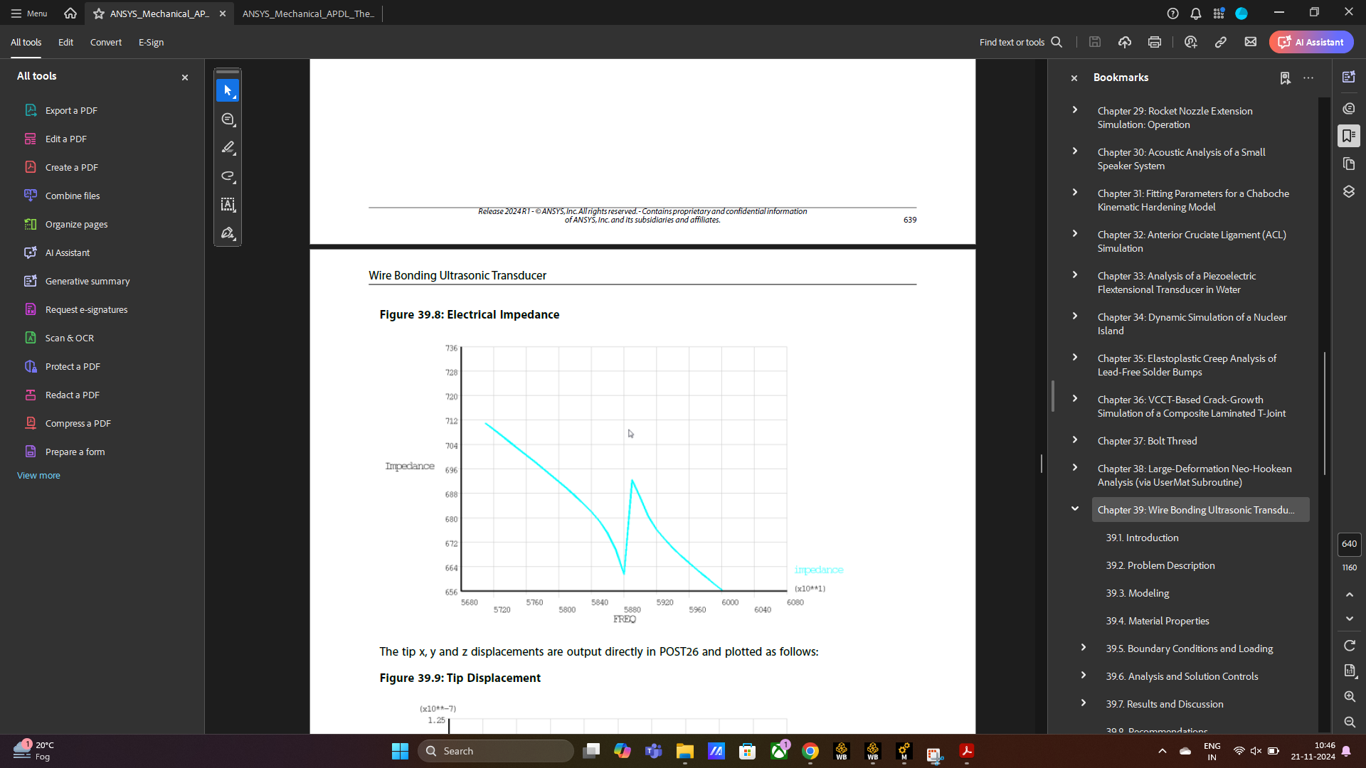
Also, from the reference given by you in the help manual for the: Mechanical Technology Showcase: Example Problems Chapter 39: Wire Bonding Ultrasonic Transducer, there is an image of Impdedance vs Frequency. I am unable to understand how to achieve this graph through ANSYS.
I would appreciate if you can provide me some solution to this. Thank you.
-
November 21, 2024 at 11:49 am
ErKo
Ansys EmployeeHi
Take away the couplings, then
Apply 1 V and one grounded voltage – you only have one Voltage you need 2 voltage bc (1 V, and ground).
See the tutorial I mentioned in my 1st post – you look at the wrong one (APDL example) - see my link it is the Mechanical example.
(Shows how to define everything)
Thank you
Erik
-
November 22, 2024 at 10:50 am
sriparna.2021rce15
SubscriberThank You for your response.
I am having doubt in the coupling section i.e.,
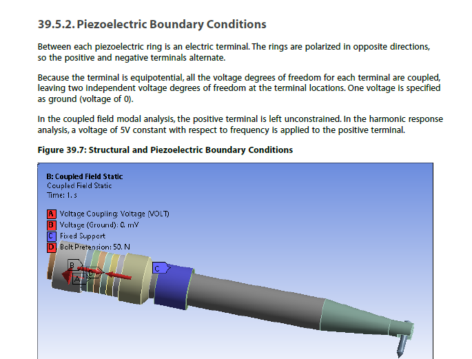
You have asked me to remove the coupling. So I removed it. But in the pdf, it is mentioned "all the voltage degrees of freedom for each terminal are coupled,
leaving two independent voltage degrees of freedom at the terminal locations." I am unable to understand this.I have removed the coupling and have applied ground voltage at the bottom surface of the PZT patch and 1V at the top surface of the PZT patch.
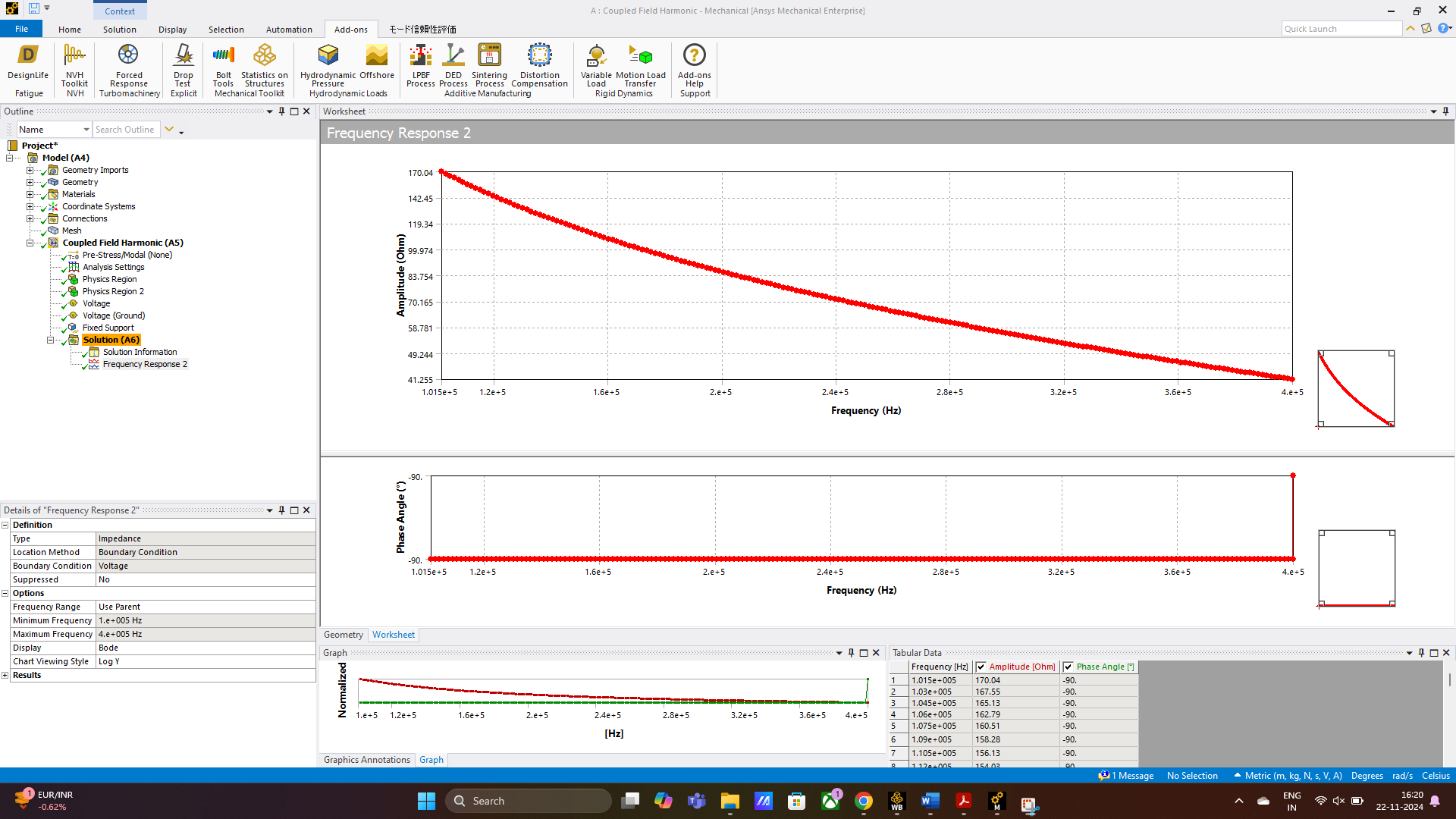
I am getting following result for Impedance, which are not correct according to me.
Kindly confirm whether this model is correct or not. Please tell me what mistakes I have done in this model
-
November 25, 2024 at 7:16 am
sriparna.2021rce15
SubscriberIt would be very helpful if any expert could provide me some solution to my problem
-
- You must be logged in to reply to this topic.


-
4612
-
1515
-
1386
-
1209
-
1021

© 2025 Copyright ANSYS, Inc. All rights reserved.

