-
-
November 19, 2024 at 7:27 am
fyoussef
SubscriberHi Everyone,
I could use some assistance here.
I am simulating heat transfer in a gearbox using the Conjugate Heat Transfer (CHT) method with two fluid phases with VoF. I’ve already defined all interfaces as one-to-one pairings with coupled walls, ensuring they don’t act as insulators. The heat sources are defined as volumetric heat sources (coupled).
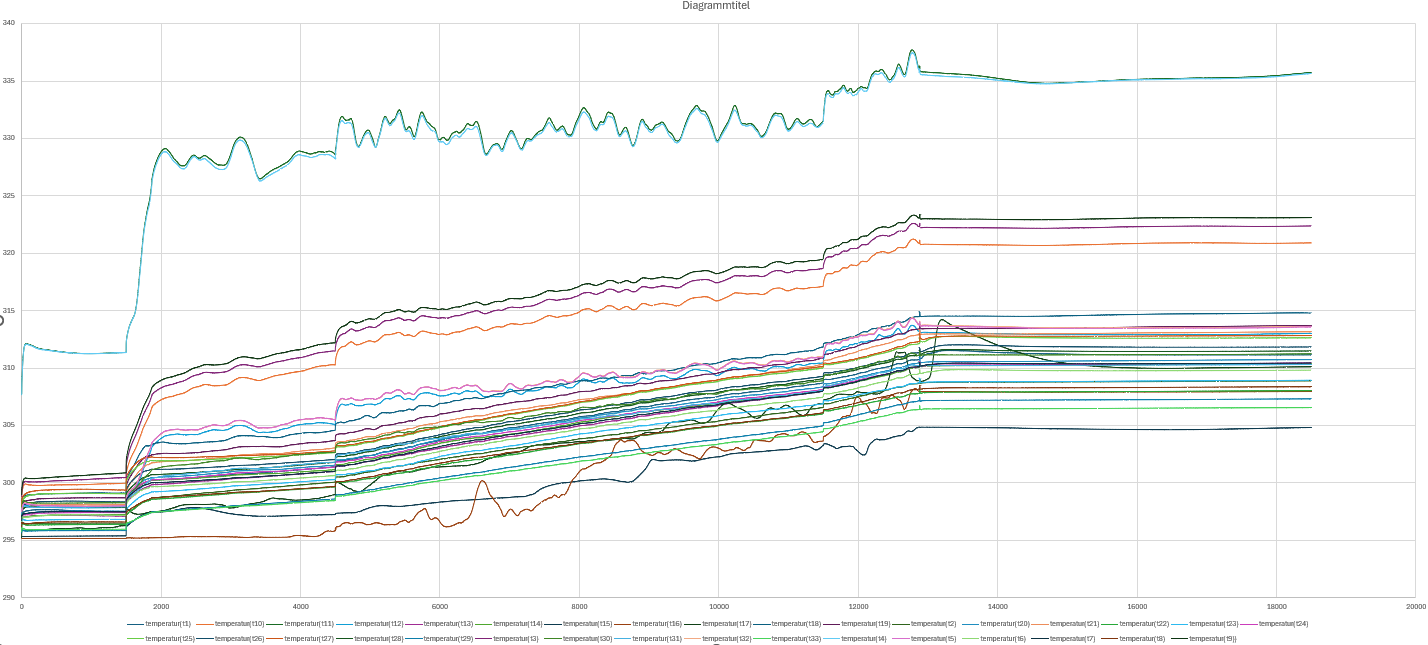
I am showing the static temperature at three different iteration numbers (Steady-State Simulation) and plotting select temperatures over iterations. While the temperature solution converges overall, especially the marked cylindrical regions remain relatively cold, colder than their surroundings even, which is unrealistic for the stationary state.
The temperature plot looks converged and there isn’t any progress anymore, but obviously fluid that is colder than all its surroundings is not “converged”. Could you please provide any advice on how to address this issue?


-
November 20, 2024 at 1:07 pm
Rob
Forum ModeratorI think you've got a few threads on this topic, this will be the last one.
Without knowing the device layout it's hard to comment, but I'd also be very wary of setting a nonconformal on the solid-fluid surface when you're looking at VOF and heat transfer. Re the cooler sections, you're correct they shouldn't drop below the minimum temperature, please check there aren't any nonzero heat flux boundaries too.
-
November 20, 2024 at 3:46 pm
fyoussef
SubscriberIt is indeed quite complicated, so thank you very much for taking the time to answer every time! 😊
What I’m simulating is actually quite simple to describe: two cylinders rotating inside a housing filled with oil and air. I’ve also included bearings and a dynamic sealing in the setup.
In the colder areas, I’m using a conformal mesh. I’ve already checked all the boundary conditions, and none of them show negative temperatures or anything unusual.
I’m simulating with a constant oil density of 1060 kg/m³, which is quite high. For the dynamic viscosity, I’ve defined a temperature-dependent expression (e.g., 0.0848 kg/m·s at 15 °C). This property is already implemented as an expression. I’ve left the air properties at their default values.
Is there any other information I should provide to make my setup clearer?
-
November 20, 2024 at 3:59 pm
Rob
Forum ModeratorNot sure, I usually use images now transparent walls are easy.
If you report all of the heat fluxes does everything balance?
-
November 20, 2024 at 4:27 pm
fyoussef
SubscriberI’m not sure if I’m allowed to share such photos; I’ll need to check with my supervisor and get back to you. I’m sorry about that, but I hope you can understand what I mean.
When I report the heat fluxes, I calculate approximately 65 W from the heat sources, which I’ve already defined. At the same time, I observe a heat loss of about -15 W due to convection with the air. Based on this, the remaining difference of approximately 50 W should stay within the system and contribute to an increase in internal energy (likely as heat)—is my understanding correct?
-
November 20, 2024 at 4:33 pm
Rob
Forum ModeratorYes, but if you're gaining 50W over time that's going to become infinitely hot.
Re the images. Academic software licences assume the work will be published, albeit not necessarily now. So you may want to check the terms of use.
-
November 20, 2024 at 4:49 pm
fyoussef
SubscriberThank you so much!
I’ll review the terms and discuss them with my supervisor. I’ll get back to you in the next few days.In the meantime, I’ll work on increasing the heat flux through convection to reach the 50 W required for system balance.
I truly appreciate your time and support
-
November 20, 2024 at 6:54 pm
fyoussef
SubscriberIt seems that the wall thickness I previously defined as 1 mm is causing the imbalance in my system. How should I define the wall thickness to ensure a balance occurs on both sides of the heat source, specifically between the wall and the wall shadow? Thank you again for your assistance!
-
November 21, 2024 at 12:02 pm
Rob
Forum ModeratorIf the wall bounds a solid and is the same as the solid I'd not give it a thickness. That's mainly used for coatings or similar where we don't want (or can't afford to) mesh the thickness. Unless there's a heat generation in the layer the energy flux should balance; ie wall & wall:shadow are the same absolute value.
-
November 21, 2024 at 1:58 pm
fyoussef
SubscriberExactly, I have heat generation within the layer, so is it normal that the heat fluxes on both sides of the layer don’t balance?
-
November 21, 2024 at 3:18 pm
Rob
Forum ModeratorYes, as heat will be pushed each way based on the adjacent cell ability to move it on so in, out + source should add up. But with the adjacent cell being the other side of a nonconformal it may become more difficult to acheive a good balance.
-
- You must be logged in to reply to this topic.


-
4678
-
1565
-
1386
-
1242
-
1021

© 2025 Copyright ANSYS, Inc. All rights reserved.


