-
-
November 11, 2024 at 7:05 am
sriparna.2021rce15
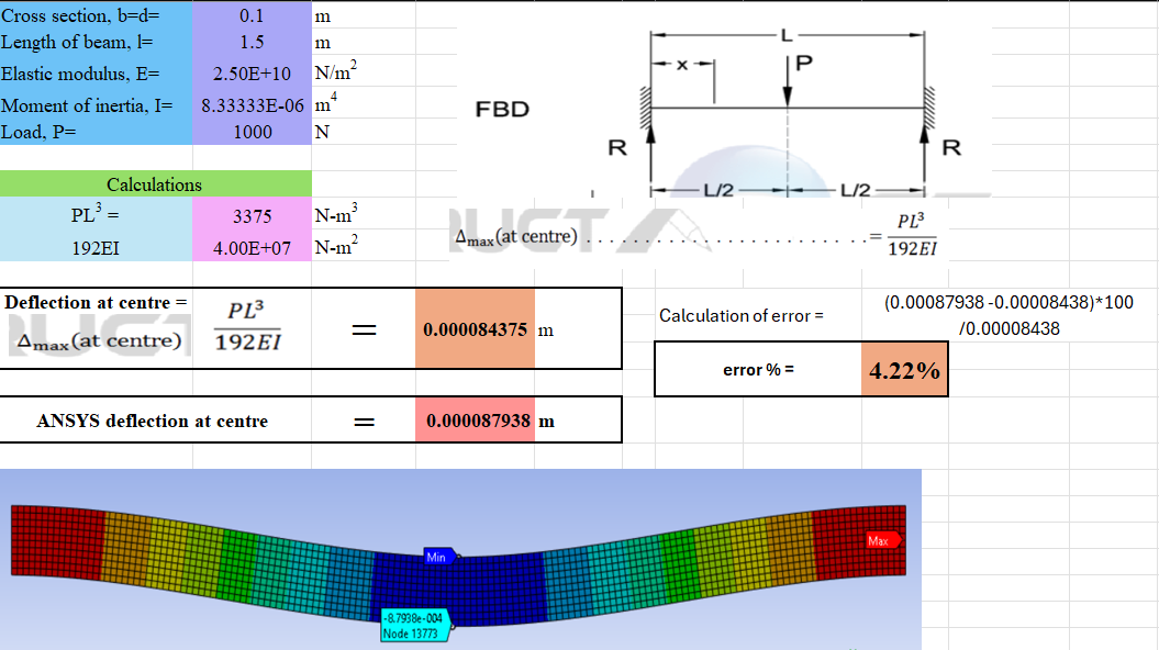
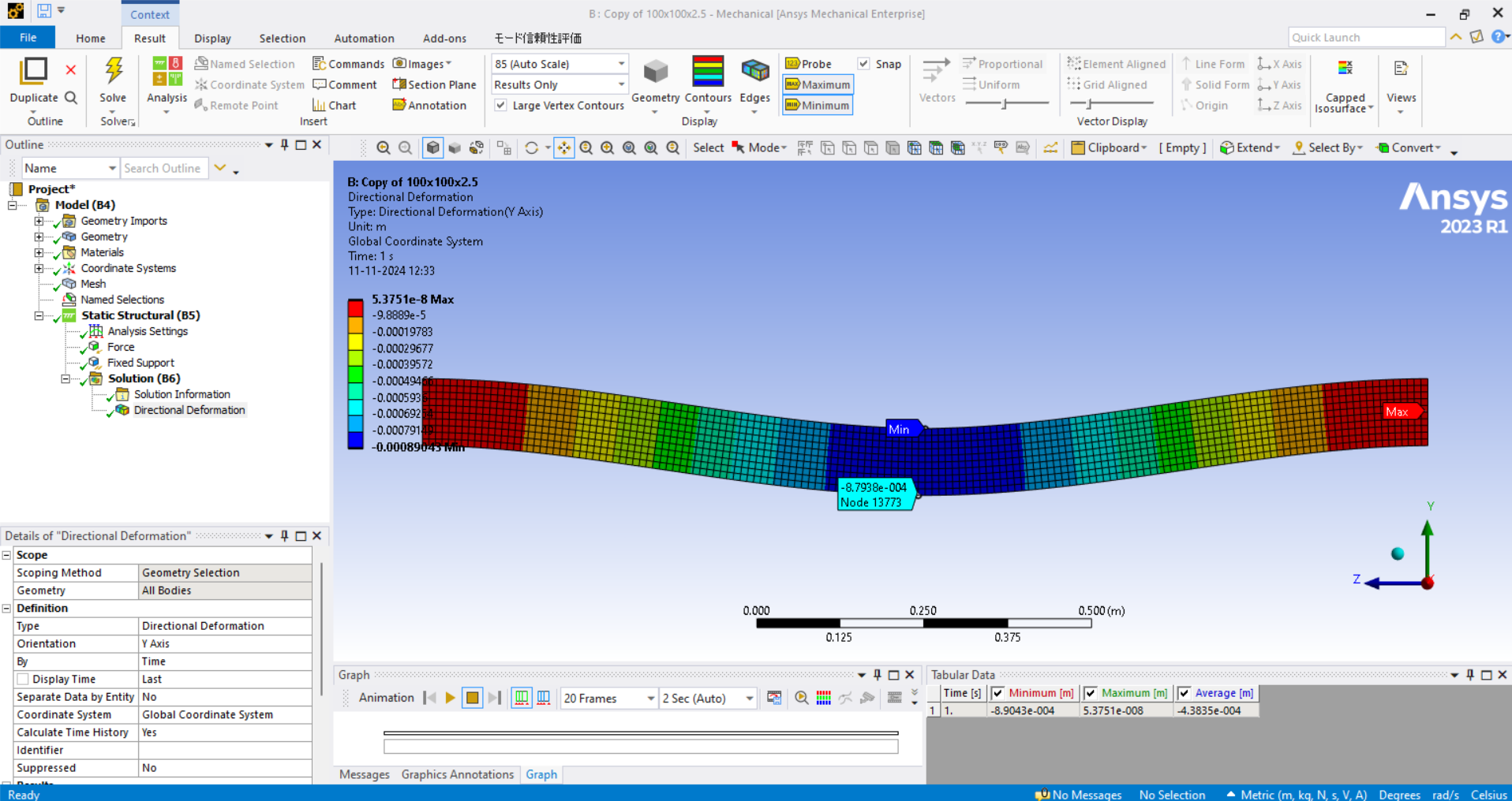
SubscriberI have modelled a fixed concrete beam with the following dimensions: 100mm x 100mm x 1.5m (l/d ratio= 15) in ANSYS workbench. The boundary condition used is fixed support. Mesh element size is 0.01m. I performed the static structural analysis on this beam. It was found that there is an error of about 4.22% in the ansys result when compared to analytical deflection values. I have attached the analytical solution and the modelled beam as well. Kindly help me out with this.
Also I would like to know that at what L/d ratio ANSYS does not consider Timoshenko beam theory.
-
November 11, 2024 at 9:53 am
mohan.urs
Ansys EmployeeHey,
The difference in the values is due to the fact that shear deformation is not included in your analytical calculation. The classic beam theory formulas do not include the deformations due to shear. If the beam is not long enough for the section, the shear deformation, which is not concidered in your calculation, is not negligible. As the result, the deformation is larger than your calculation.
Check out this course which explains why there is a difference between them and also validates it.
https://innovationspace.ansys.com/courses/courses/a-non-slender-cantilever-beam-under-point-tip-loading/You can try using classic beam elements instead of solid elements (current case) if you want to match the values. And also since you are using solid elements Timoshenko beam thoery is not applicable for them. For more info on beam elements which use Timeshenko theory check out theses links.
5.3. Beam and Link (Truss) Elements
https://ansyshelp.ansys.com/public////Views/Secured/corp/v242/en/ans_elem/Hlp_E_BEAM188.html
https://ansyshelp.ansys.com/public////Views/Secured/corp/v242/en/ans_elem/Hlp_E_BEAM189.htmlRegards,
Mohan Urs -
November 12, 2024 at 6:41 am
sriparna.2021rce15
SubscriberThank you for your response.
As you stated "If the beam is not long enough for the section, the shear deformation, which is not concidered in your calculation, is not negligible." I would like to know at what length would be enough so that shear deformations can be neglected i.e., what should be the l/d ratio.
Also, if I have used SOLID186 element and shear deformations are not taken into account by solid elements. Then the analaytical results should match in case of solid elements
-
- You must be logged in to reply to this topic.


- LPBF Simulation of dissimilar materials in ANSYS mechanical (Thermal Transient)
- Real Life Example of a non-symmetric eigenvalue problem
- How can the results of Pressures and Motions for all elements be obtained?
- BackGround Color
- Contact stiffness too big
- Element Birth and Death
- Python-Script to Export all Children of a Solution Tree
- Which equations and in what form are valid for defining excitations?

-
4597
-
1495
-
1386
-
1209
-
1021

© 2025 Copyright ANSYS, Inc. All rights reserved.


