-
-
November 9, 2024 at 9:58 am
javat33489
SubscriberHello everyone.
I am calculating the wheel.
I used the following contacts:
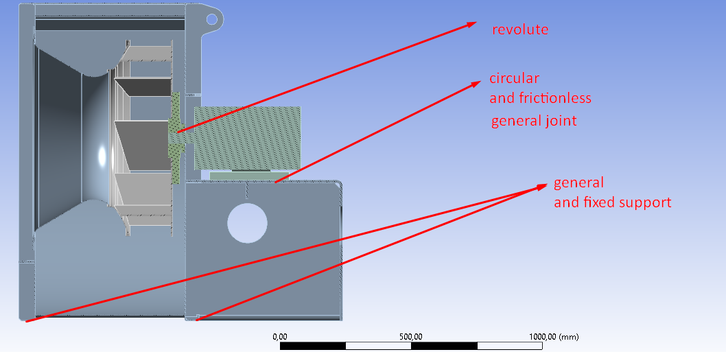
- wheel to the motor shaft - joint revolve body-body
- so that the engine does not rotate from the revolve, I attached its paws to the body using - joint general body-body and marked everything free
- so that the body on which the engine is located does not rotate, I secured it from below using joint general body-body and secured it along the Z axis (and the hole where it is fixed with bolts is fixed support).
Thus, only the wheel rotates and everything else is fixed.
There is a frictionless contact between the shaft and the wheel, the wheel is as if put on the shaft.
There is a frictionless contact between the engine feet and the housing, but the foot holes are fixed to the housing holes with circular beams (imitation of bolts).Problems:
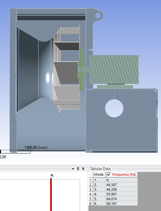
1. I make a static calculation of the rotation of the wheel of a rotational velocity of 1500 RPM, and then I make a modal analysis from the static (presterss), but why does the wheel have a mod of 0??? This means that it is not fixed??? But it is fixed with joints and stands on the shaft.If I put not a revolution but a fixed joint between the shaft and the wheel, then there is no 0 mode. Maybe the modal analysis does not see the rotation of the rotation velocity of 1500 RPM?
1.1. Is it possible to fix one of the bodies from mutual rotation without additional joints when specifying a revolution?
2. I display the results of the circular beam stress but I see 0, in addition, I see an error that the data for the result is incorrect:
Maybe the general joint is in the way?
-
November 9, 2024 at 1:22 pm
peteroznewman
SubscriberThe wheel is free to spin on the shaft. That means there is zero stiffness in the rotational direction, which results in a zero frequency. After you change the revolute joint to a fixed joint, the wheel now has a stiffness to ground in the rotational direction and you get a non-zero frequency. I explained how the intertial load of rotational velocity works in your other discussion.
-
November 9, 2024 at 2:25 pm
javat33489
SubscriberYou are right.
The wheel rotates freely on the shaft, but I do prestress, in the previous calculation it did not rotate freely, it rotated under the action of rotation velocity.
-
-
November 9, 2024 at 3:21 pm
javat33489
SubscriberSir, I figured it out, thank you.
If the degree of freedom is not fixed, then no amount of prestress will remove it. -
November 9, 2024 at 4:52 pm
peteroznewman
Subscriber"it rotated under the action of rotation velocity." I'm not sure you fully understand how the Inertial load Rotational Velocity works in a Static Structural analysis. Know this: the body that the load is applied to can be fixed to ground in all degrees of freedom and in that case, there will be no rotation of the wheel. Reread my replies in your other discussion.
-
- You must be logged in to reply to this topic.


-
4683
-
1565
-
1386
-
1242
-
1021

© 2025 Copyright ANSYS, Inc. All rights reserved.


