-
-
November 8, 2024 at 8:17 pm
javat33489
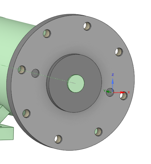
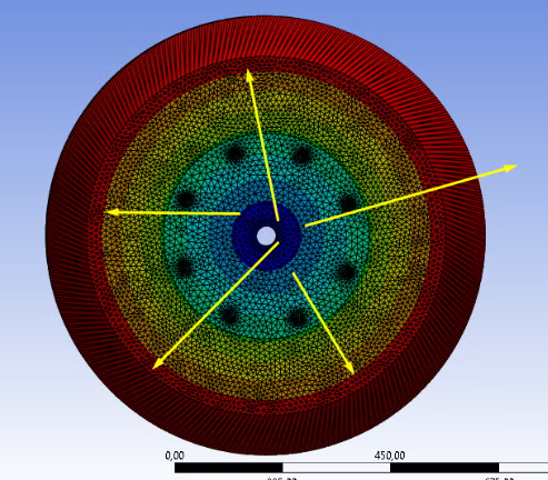
SubscriberIf I set 1500 RPM for wheel rotation and set the standard calculation time to 1 sec, can I assume that I will get stress for 1500 RPM/60 Sec = 25 revolutions? Static structural module.
Is this setting sufficient to estimate the wheel stress at the specified speed?
-
November 9, 2024 at 1:34 am
peteroznewman
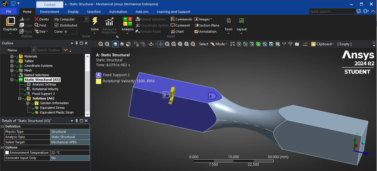
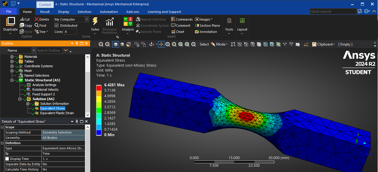
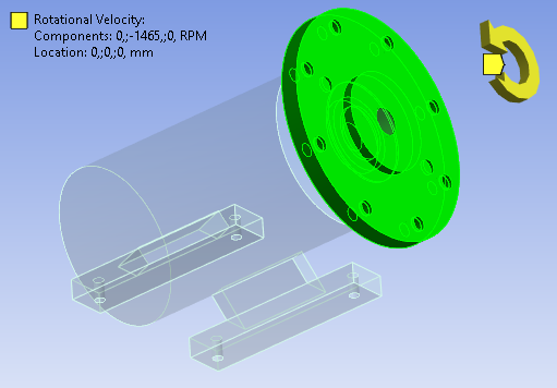
SubscriberIn Static Structural, you can compute the stress due to the centrifugal force = m omega^2 r acting on each element for a wheel spinning at 1500 RPM by using the Inertial load of rotational velocity. This load can be applied to a wheel that has a fixed support at the center hole of the wheel. The wheel does not rotate during the simulation. You will see a slight radial deformation due to the centrifugal force caused by the rotational velocity inertial load. You correctly converted RPM to revolutions/second.
-
November 9, 2024 at 9:39 am
javat33489
SubscriberThanks for the reply sir. I didn’t quite understand how to do it. Will it be user defined result: m omega^2 r?
Do I need to use rotation velocity = 1500 RPM + m omega^2 r?
Can you tell me more? Do I need to apply rotation velocity?UPD.
Sir, perhaps I did not understand you? Did you mean that I did everything correctly? And you answered my question that I will not see rotation in the result.
-
-
November 9, 2024 at 12:35 pm
peteroznewman
SubscriberRotational Velocity can be input as omega in radians/sec, but you can set the units to enter RPM directly. The object needs to be fixed to ground.
Rotational Velocity requires the axis of revolution so the solver knows the radial dimension "r" of each node from the axis. The solver knows the mass m of each element so it calculates a force on each node according to the equation m omega^2 r.
That force causes deformation that causes stress. There is more deformation if the RPM is increased. There is more deformation the further the node is from the axis of rotation.
-
November 9, 2024 at 1:29 pm
-
-
November 9, 2024 at 1:36 pm
peteroznewman
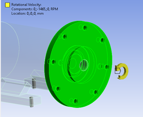
SubscriberThe Inertial load of Rotational Velocity is applied to bodies not to faces. All the mass in the selected body experiences a centrifugal force. The housing which is not selected does not experience any centrifugal force.
-
November 9, 2024 at 1:38 pm
javat33489
SubscriberSir, the wheel rotates on a fixed shaft, won't the inertia from it be transferred to the shaft? I can't select the shaft by rotation either, it is fixed.
-
November 9, 2024 at 1:40 pm
javat33489
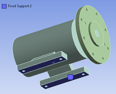
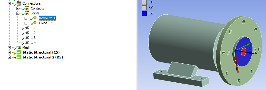
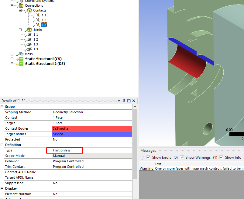
SubscriberSir, I set the rotation on the wheel, I set the contact between the wheel and the shaft without friction, and so that the wheel does not fly into space, I made a joint between the wheel and the shaft to rotate. Is this wrong? I need to understand how the shaft will behave when the wheel rotates on it
-
-
November 9, 2024 at 2:11 pm
peteroznewman
SubscriberNotice in the example I showed where there is only one body, it is both Fixed to ground so it can't spin about the axis that was defined using an edge, and also experiences the load it would see as if it was spinning about that axis. Notice that the free end of the body bends away from the axis because the centrifugal forces are pulling each node away from the axis.
In my example with one body, the body is eccentricly positioned relative to the axis of rotation. Imagine that body was bolted to a shaft on the axis of rotation, and that shaft was supported by bearings in a housing fixed to ground. You could apply a Rotational Velocity to the body, shaft and bolts, and they would flex outward and the frame would experience the reaction force at the bearings supporting the shaft, but the frame would statically deflect in the direction the body was being pulled. This is the limitation of Rotational Velocity, nothing is actually rotating. In the real world, the eccentric mass rotates so the force on the housing bearings also must rotate. One way to do this is to use a joint load on the shaft of angular position in steps of 15 degrees to look for the worst case stress in the housing for a full 360 degrees of angles of the shaft about its axis.
-
November 9, 2024 at 2:15 pm
-
November 9, 2024 at 4:35 pm
peteroznewman
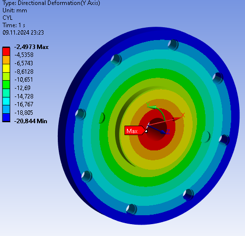
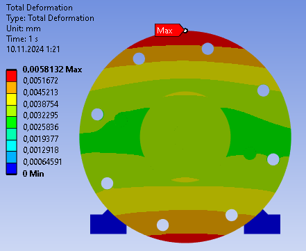
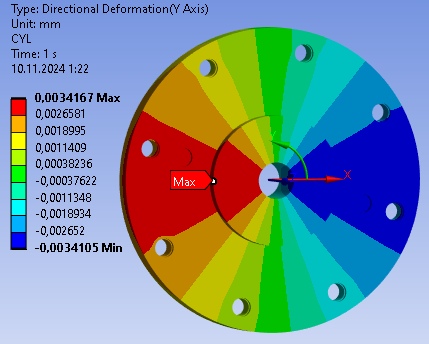
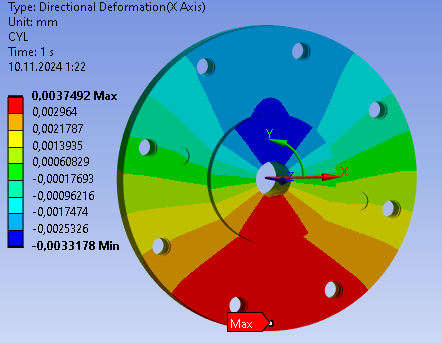
SubscriberI don't believe the deformation plot with 6.5 mm of total deformation is correct, I think most of that deformation comes from rotation of the wheel. Create a cylindrical coordinate system with Z along the axis of the shaft and plot the radial directional deformation (X axis). That should be a tiny fraction of a mm. Plot the tangential directional deformation (Y axis) and that will be the 6.5 mm.
Try suppressing everything in your model except for the wheel. Use a Fixed Support on face of the hole in the center. The total deformation should be a tiny fraction of a mm.
-
November 9, 2024 at 6:24 pm
-
November 9, 2024 at 6:46 pm
peteroznewman
SubscriberThis shows 2.5 mm of tangential movement at the face of hole in the center of the hub and 20.8 mm of tangential movement at the rim of the wheel. This means that the wheel is not fixed in rotation. When you fix the rotation, the radial displacement should become a small positive value at the rim. The large negative radial displacement is an artifact of allowing rotation.
-
November 9, 2024 at 7:02 pm
-
November 9, 2024 at 8:14 pm
peteroznewman
SubscriberChange the Revolute joint to a Fixed Joint. Change the Frictionless Contact to Bonded Contact. Then the Wheel cannot rotate. Then the Inertial load of Rotational Velocity should give a tiny positive radial directional deformation.
-
November 9, 2024 at 8:22 pm
-
November 9, 2024 at 8:25 pm
javat33489
SubscriberWhen I was learning, a long time ago. For some reason I forgot that when installing rotational velocity, you need to secure the wheel from rotating.
Thank you. Now I know everything.
-
-
November 9, 2024 at 2:21 pm
javat33489
SubscriberThank you for your answers sir.
I have one more question, the last one.
After I give such a calculation in the static module, with fixings as I said:Sir, I set the rotation on the wheel, I set the contact between the wheel and the shaft without friction, and so that the wheel does not fly into space, I made a joint between the wheel and the shaft to rotate. Is this wrong? I need to understand how the shaft will behave when the wheel rotates on it
Then I make a modal analysis from the static (pressure stress) this is necessary to understand the first mode, for seismic calculations.
But for some reason it is the wheel that shows mode 0. As if it is not fixed, could this be due to rotation? Why is that?-
November 9, 2024 at 3:23 pm
javat33489
SubscriberSir, I have sorted out the mod issue, thank you.
-
-
November 9, 2024 at 3:28 pm
javat33489
SubscriberSir, and if I apply torque to the inner diameter of the wheel, for example, I wrote earlier that I use a revolution so that the wheel does not move from its place, if I use this joint to rotate using torque, instead of rotation velocity, then I cannot get the result, the wheel swells greatly and an error occurs.
Previously, I applied 1500 RPM, and if I apply torque, this is 95,000 Nmm according to my engine data.The question is, are these tools interchangeable, joint-torque and rotation velocity?
And why does the wheel swell so much with torque? despite a good grid, large movements and many steps. -
November 9, 2024 at 4:01 pm
javat33489
SubscriberThe question is as follows.
I have a motor with a rotation speed of 1500 RPM and a torque of 95 Nm.
I tried to use the torque, but then my model falls apart as I described above, then I used the rotation speed, everything works well.
Did I do everything correctly? Can I replace it?
-
-
November 9, 2024 at 5:20 pm
peteroznewman
SubscriberIn one reply, you say the shaft is fixed and the wheel spins on the shaft. In another reply, you apply a torque to the wheel. To do that, the wheel could be fixed to the shaft and the engine on the other end of the shaft delivers that torque. I suppose there could be a clutch between the wheel and the shaft to disengage the wheel from the engine.
There are a limited number of answers you can get from a Static Structural analysis. The stress in a body rotating at a constant speed is one of them. In that case, the wheel is fixed to the shaft, but the rotation of the shaft should be fixed.
Transient Structural analysis is used to apply a torque to the engine-end of a shaft-wheel assembly and observe it speed up from rest over time. In that case, the wheel is fixed to the shaft and the shaft is free to rotate on its bearings. Note that you have to limit the end time of the simulation because the RPM will increase without limit the longer the torque is applied unless some viscous rotational damper is in the system to build up a large opposing torque to let the system reach equilibrium.
-
November 9, 2024 at 6:01 pm
javat33489
SubscriberSir yes, I made the shaft fixed and rotate the wheel on it either by rotation speed or torque.
I made the shaft fixed because it is simpler and the solution is faster than the shaft rotating inside the engine and also rotating the wheel. By rotating the wheel on the shaft I simulate rotation to simulate the transfer of load to the housing of the conditional engine and then to the bolts that hold it.I understand sir, the application of rotation speed is the best option for static analysis.
-
-
- You must be logged in to reply to this topic.


- LPBF Simulation of dissimilar materials in ANSYS mechanical (Thermal Transient)
- Real Life Example of a non-symmetric eigenvalue problem
- How can the results of Pressures and Motions for all elements be obtained?
- BackGround Color
- Contact stiffness too big
- Element Birth and Death
- Python-Script to Export all Children of a Solution Tree
- Which equations and in what form are valid for defining excitations?

-
4592
-
1494
-
1386
-
1209
-
1021

© 2025 Copyright ANSYS, Inc. All rights reserved.

