-
-
November 4, 2024 at 2:36 am
mcamp1
SubscriberHello,
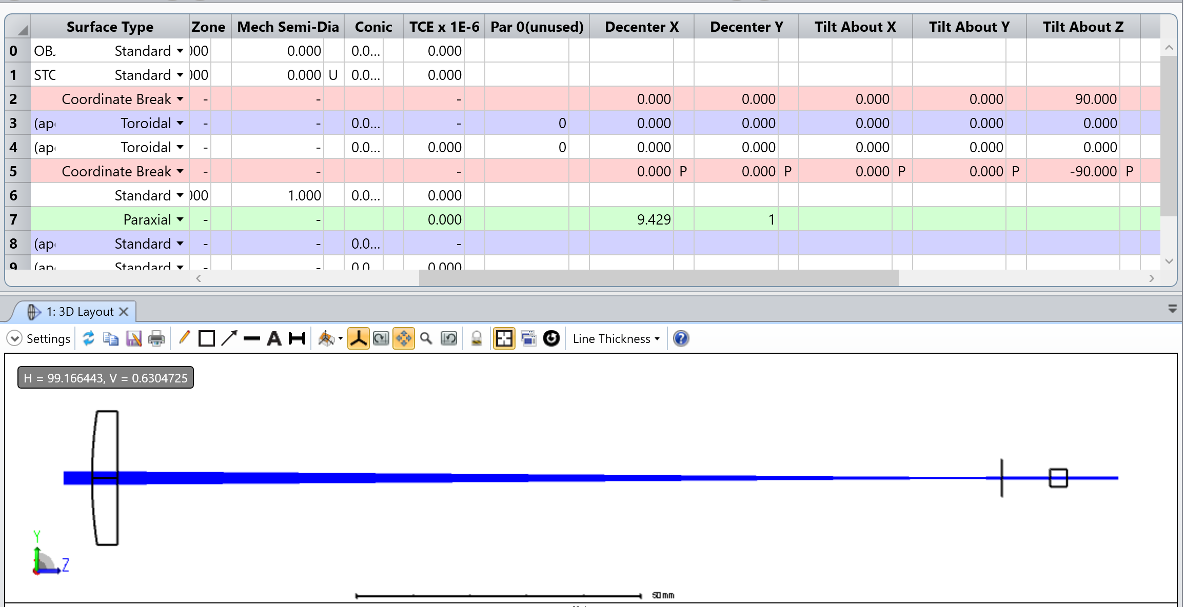
I'm trying to rotate a cylindrical lens by 90 degrees so that a different axis of the beam is focused. This is the system before any coordinate breaks:
I want to have the beam collimated before the paraxial lens and then converge/diverge afterwards. This requires a rotation of the cylindrical lens. However, rotating the lens doesn't affect the beam, and instead affects the subsequent surfaces. This:
Results in this:
Where you can see that the final surface has changed while the beam shape has not. Am I doing something wrong with the tilt? The coordiante break is setup to have 90 degree tilt in z and -90 tilt afterwards.
-
November 4, 2024 at 10:32 am
Niki Papachristou
Forum ModeratorHi Subscriber,
I am a little bit confused here, with the Tilt/Decenter elements tool I would expect the element to be tilted and not the subsequent surfaces. It would be good to go through this Knowledge base article to make sure you are using the tool properly in order to achieve your design goals: How to tilt and decenter a sequential optical component. Additionaly, I have difficulties on noticing the differences between the LDE of your first case with the LDE on your second case.
Another reason that I can think of why you dont see a collimated beam is the fact the your EPD is smaller than the lens diameter.
Hope that was helpful, let me know if I can be of further assistance.
Regards,
Niki
-
November 4, 2024 at 1:53 pm
mcamp1
SubscriberHello,
Thanks for the response! The difference between the two LDEs is that in the first one, the Coordinate Breaks have 0 for Tilt about Z. The second LDE has 90 and -90 for Tilt about Z. All I hope to achieve is a 90 degree rotation of one element, so I believe this should be enough.
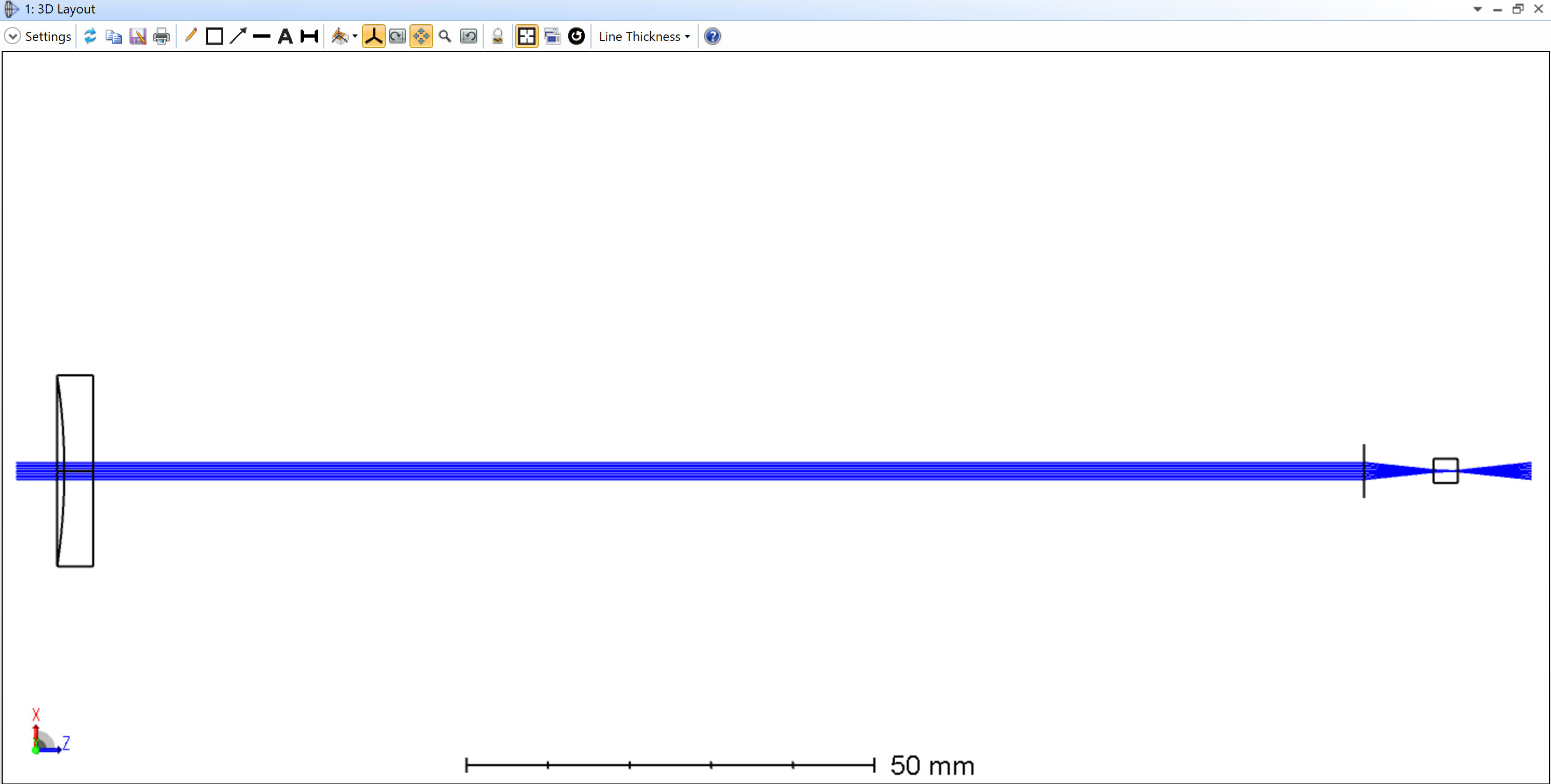
I’m attaching a picture of what I hope to achieve by rotating:
As you can see the beam can be collimated, it's just currently in the wrong axis. This screenshot was achieved by rotating the entire coordinate system in the 3D Viewer, but I would expect to see the same results by only rotating the cyindrical lens in the LDE.
-
-
December 27, 2024 at 11:23 pm
Kirill
Forum Moderator -
January 6, 2025 at 10:08 pm
mcamp1
SubscriberHello, thank you for the response.
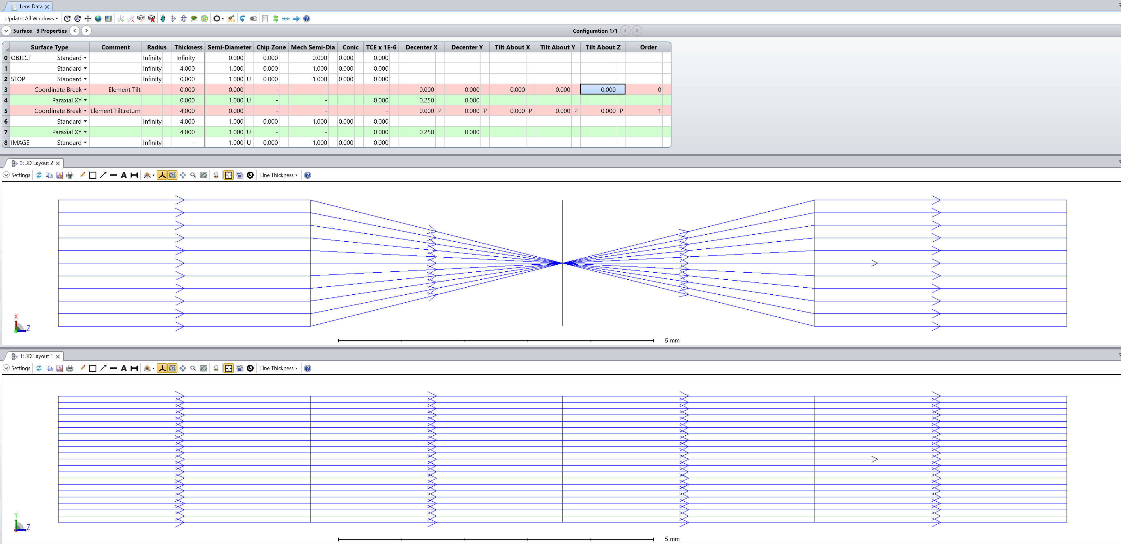
What I am still confused about is: why do the rays not appear to change before the second cylindrical lens in your example? What I would like to do is rotate a single cylindrical lens such that the axes the rays converge and collimate in will switch.
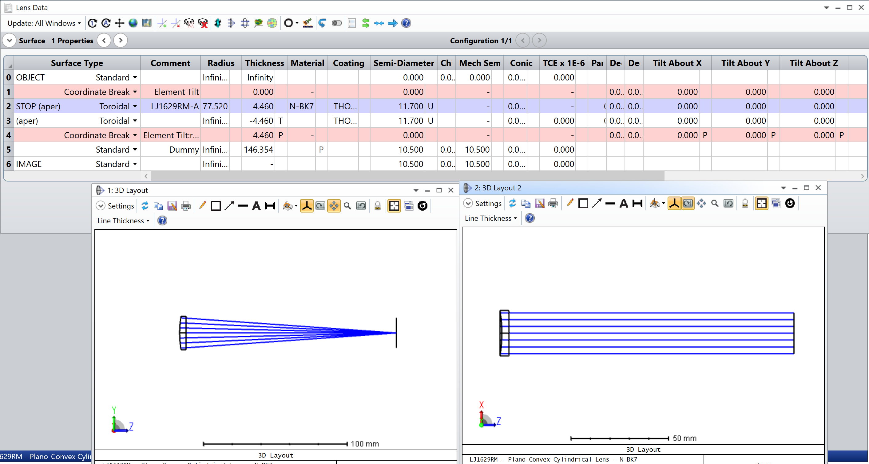
In your example, when the first lens is not rotated, (ignoring the second lens for now) the rays converge in the first orientation and are collimated in the second orientation. I would like for a single lens rotation to collimate the rays in the first orientation and converge the rays in the second orientation.
I attached an example of what I am talking about. A setup with a single lens should still change the beam right? I have not seen a difference whether I set tilt to 0 or 90 degrees.
-
January 6, 2025 at 11:07 pm
Kirill
Forum ModeratorDear Subscriber,
Please note that you are observing different plane projections of a 3D geometry. In your case, the cylindrical lens focuses in the YZ plane but does not in the XZ plane. Switching to an isometric view will likely reveal something like this:
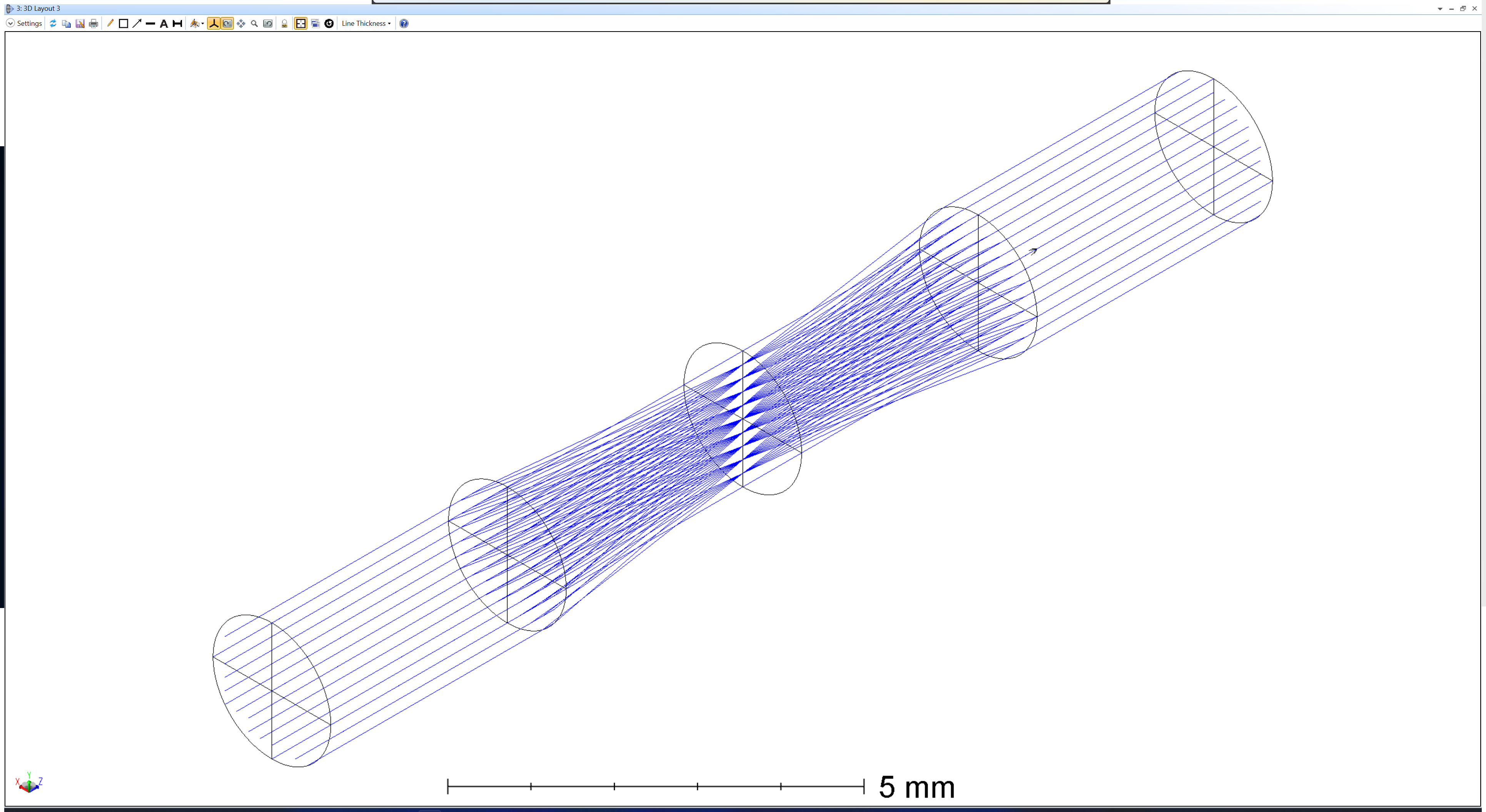
Additionally, while not the case here, the view can sometimes be misleading due to the Ray Pattern selection in the 3D Layout > Settings. For instance, in my setup, selecting "Y Fan" causes the layout to appear as a 'single ray' in the XZ projection, which is still accurate.

Hope this helps.
Best regards,
Kirill -
January 7, 2025 at 10:26 pm
mcamp1
SubscriberHi, thanks for the response!
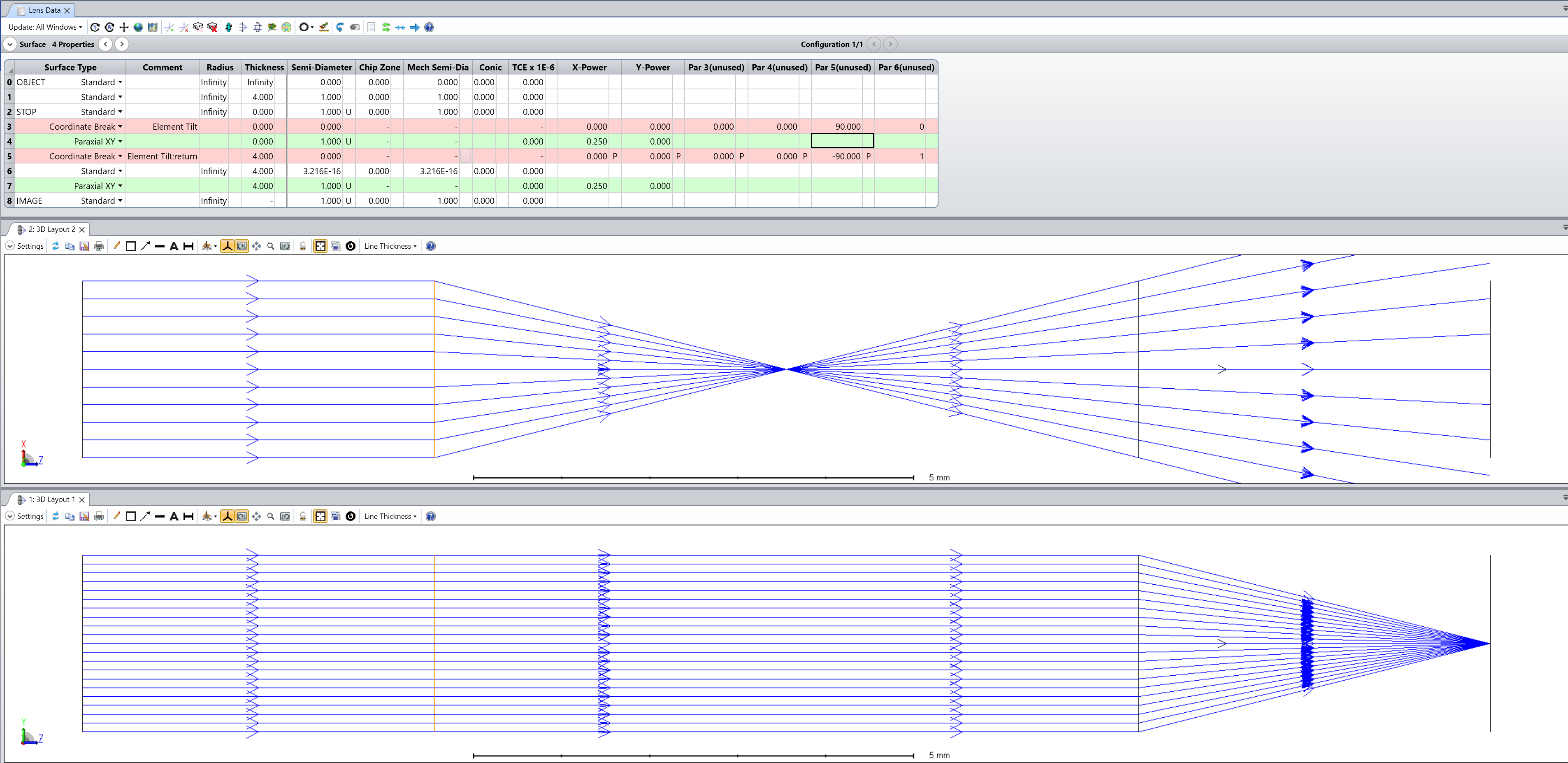
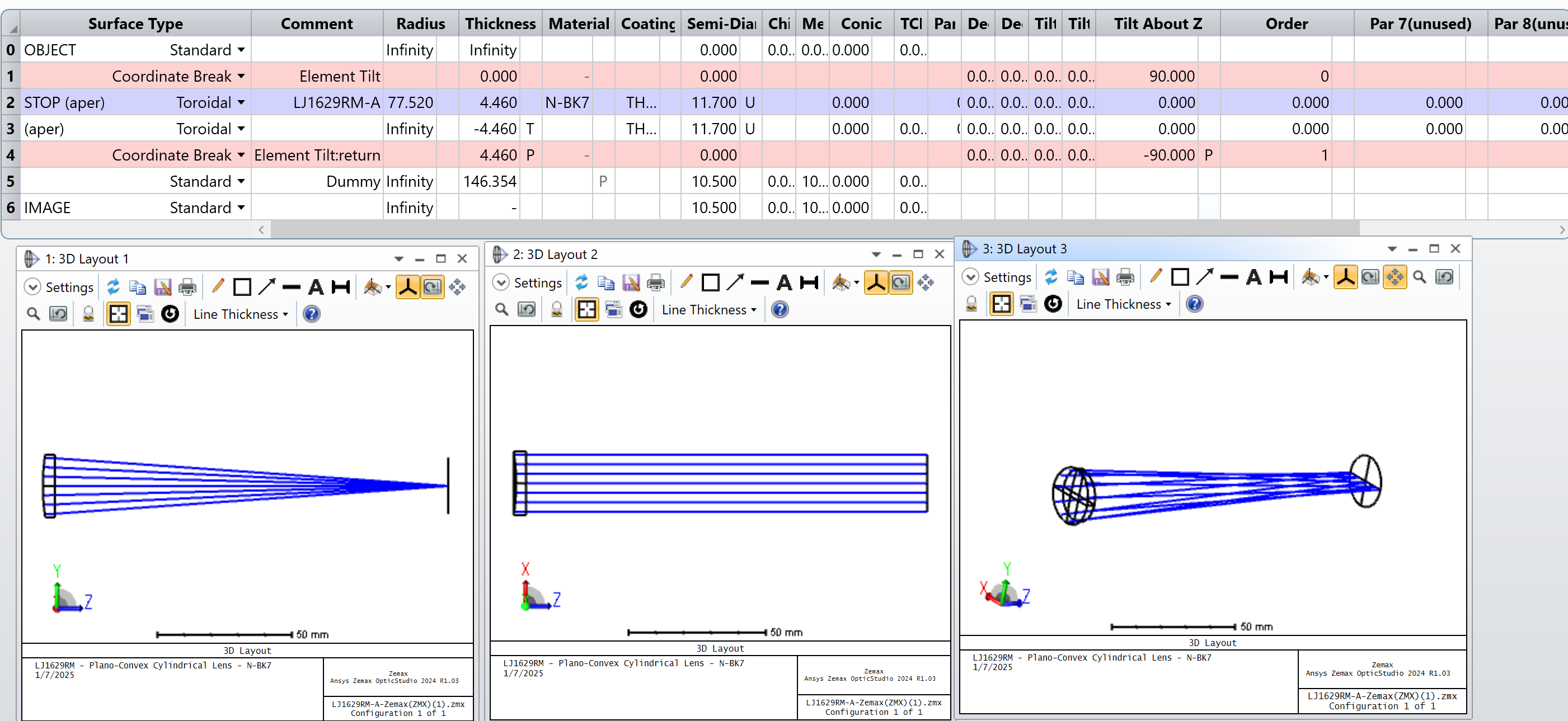
I do understand the two projections are different, that is intentional. Like you said, the lens focuses in the YZ plane and does nothing in the XZ plane. I would like to flip this so that the lens focuses in the XZ plane and does nothing in the YZ plane. However, in the picture below you can see that even though I now add a 90 degree tilt to the cylindrical lens, the projections are the same as before. Do you know why this is? The ray patterns are XY fan and ring, so that shouldn't be an issue.
-
January 8, 2025 at 12:04 am
Kirill
Forum ModeratorDear Subscriber,
Thank you for checking! That was very helpful.
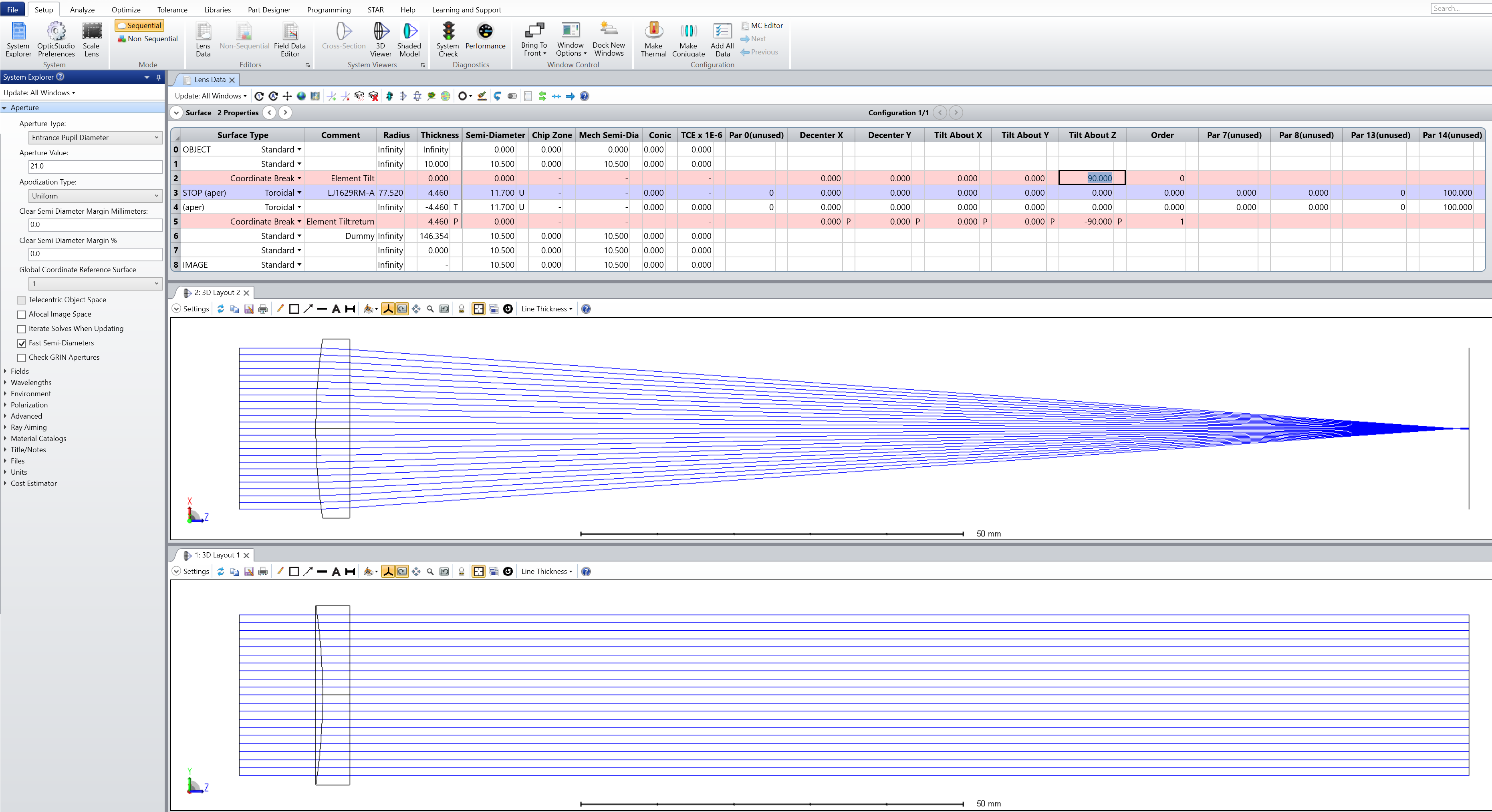
Now, please navigate to System Explorer > Aperture and verify which surface is set as the Global Coordinate Reference Surface. My guess is that, in your case, it is set to '2.'
Try changing this setting.When you load the catalog lens, the Global Reference is initially set to surface 1 and remains unchanged even after you add a Coordinate Break.
Best regards,
Kirill -
January 8, 2025 at 4:17 am
mcamp1
SubscriberHello, just wanted to confirm that this seems to have fixed the issue! Thanks, that helped a lot :)
-
January 8, 2025 at 12:35 pm
Kirill
Forum ModeratorI'm glad it helped! Please consider marking this thread as 'answered' to make it more visible to other Forum users. Thanks!
-
- You must be logged in to reply to this topic.


-
4492
-
1494
-
1376
-
1209
-
1021

© 2025 Copyright ANSYS, Inc. All rights reserved.


