-
-
October 31, 2024 at 2:49 pm
Kelsey O'Donnell
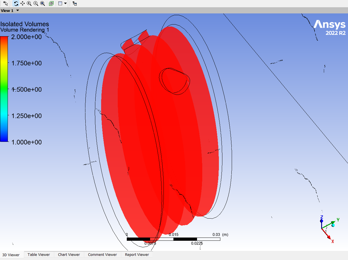
SubscriberI am trying to simulate external and internal flow however whenever I try to setup my simulation (including setting a wall on all of the other interior volume's faces besides the inlet/outlet) I always get an error saying there are two isolated fluid regions and the solver cannot compute. In my initial CFX-Pre window, it says my domain has two fluid-fluid interfaces. I go to those and under non-overlap conditions I set these interfaces to a no-slip wall. I then set the rest of my boundary conditions as normal (velocity inlet and 0Pa opening for the bounding box and the internal volume and no-slip walls for all other surfaces). What am I missing in my setup that causes this error?
-
October 31, 2024 at 3:13 pm
Mark O
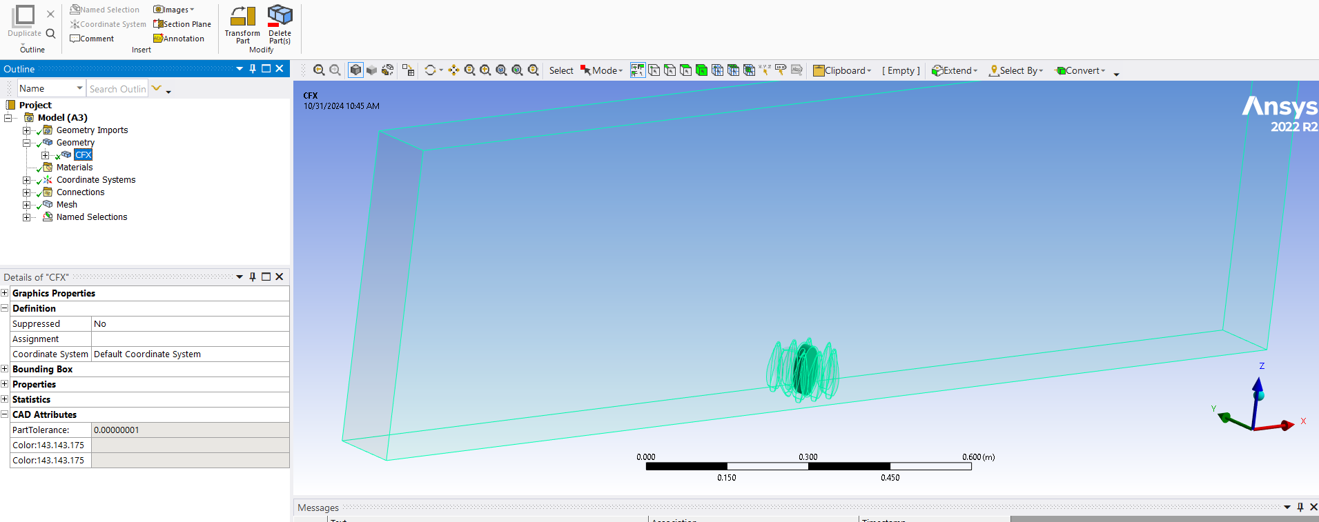
Ansys EmployeeHi, Ansys meshing will mesh each part separately with a separate mesh on each side of shared part faces. It will create connections in the connections part of the tree in your picture above that automatically get turned into mesh interfaces when the mesh read into CFX-Pre. That should not result in isolated regions but it is possible that you accidentally turned the entire mesh interface into a wall and not just the non-overlap region. The non-overlap region is a wall by default so there should be no need to change and settings for the mesh interface in CFX-Pre. If you do not want to have any mesh interfaces then in DM put all the solids into the same part or in Spaceclaim turn on share topology for the top level object.
-
October 31, 2024 at 4:33 pm
Kelsey O'Donnell
SubscriberHi Mark,
Thanks for the reply. I did use the imprint tool for the inner volume and the outer enclosure but when I click share it says that there is no coincident topology. I have also had other issues with enclosures where I did not have an internal volume and I still received the isolated fluid regions error in the solver manager. For those cases I had to change the geometry selected in the default domain to only being the enclosure (not the bodies within) to fix the issue. I can't do that in this case, however, as the inner volume is of interest and I would like for it to "pump" as external flow goes around the other solid bodies
-
-
October 31, 2024 at 4:41 pm
Mark O
Ansys EmployeeIt is possible then that you do not have properly connected regions. Are you using DesignModeler or Spaceclaim for the geometry? Please refer to the training materials and tutorials for those products. In DesignModeler you can use the Boolean tool to subtract one solid from another. In Spaceclaim you can use the combine/cut tool. You must create a geometry that is composed of tessellating solids with no overlaps or unconnected faces. You know you have done this successfully if Ansys meshing reports that there are no connections.
-
October 31, 2024 at 4:52 pm
Kelsey O'Donnell
SubscriberHi Mark,
I am using SpaceClaim and creating an Enclosure around the objects I want to simulate external flow around. I am then disabling those solid objects before going to the mesher as to just focus on the fluid enclosure. Do I need to create an enclosure and then use the combine tool? The solids I am using are CAD geometries that were originally .stl files that I used the AutoSkin tool on in SpaceClaim. They have no overlaps or unconnected faces.
-
-
November 1, 2024 at 9:32 am
Mark O
Ansys EmployeeHi, the enclosure tool can be a bit brittle. You have to respect the logical relationship between its objects and must never separate its objects or you will break the enclosure. As an alternative in Spaceclaim create solids with the no merge option to create overlapping solids and use the combine tool with the saw option to subtract one solid from the other. Then turn on share topology for the root object in the structure. This is more flexible than the enclosure tool. Try a practice by creating one cube inside another. You know it worked if Anysys meshing reports there are no contact regions. The mesh will then be fully connected.
-
November 1, 2024 at 2:21 pm
Kelsey O'Donnell
SubscriberHi Mark,
I am able to do this and there is simply a check next to connections in the mesher but no connections present. My concern, however, is that I am trying to enclose hundreds of individual solids to simulate flow through a "mussel" aggregation, will doing this method instead of the enclosure cause a lot more computational power of this simply how I need to create it no matter what? Also does this work if I would like to have an internal volume as well? Should I simply be setting the outer box material to liquid? Sorry for all the questions!
-
November 1, 2024 at 2:37 pm
Kelsey O'Donnell
SubscriberHi Mark,
I have run into another issue with this method, which is that I am now once again getting an isolated fluid regions error causing my solver to fail
-
-
November 1, 2024 at 2:44 pm
Mark O
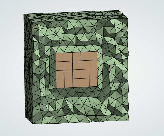
Ansys EmployeeHi, in my picture above there is an internal volume in brown and an external volume in green. The geometry doesn't care what the regions will later be assigtned to. At the geometry stage all you are trying to do is fill a domain with tessellating solids and assigning names to them and some of their faces. I can't see how that would result in an isolated fluid error in CFX unless you have failed to produce a connected mesh. There is a limit to how much help we can provide through the forum. Are you able to raise a support request?
-
November 1, 2024 at 3:51 pm
Kelsey O'Donnell
SubscriberHi Mark,
Okay it seems like the issue may be with my mesh then instead. I do believe I am able to raise a support request, I am on an academic research license. Does that matter or is anyone able to?
-
-
November 1, 2024 at 4:39 pm
Mark O
Ansys EmployeeOK, then I don't think you can raise a support request. The probem seems to be with the complex nature of the geometry. Maybe practice with a more simple one first. Ultimately, if the geometry is properly connected with share topology working properly, then Ansys meshing will report that there are no contact regions. So you should know at the meshing stage whether it is working. Then when CFX reads in the mesh it will not create any mesh interfaces. The default domain boundary should then only be composed of the exterior faces of the entire flow domain. You cannot get an isolated region error in that case except by creating walls that close off one region from another. As you start creating boundaries in CFX-Pre (inlets, outlets, walls, etc) those faces will be removed from the default boundary. If you create an explicit boundary for all the faces of the domain the default boundary will dissapear. So maybe create all the boundaries you think you should have and see whether there are any faces left in the default boundary and where they are.
-
November 1, 2024 at 4:46 pm
Kelsey O'Donnell
SubscriberHi Mark,
I believe my issue then is that I am creating walls to separate the "mussel" geometry from the outer fluid domain. Specifically I am selecting and am setting all of those faces that make up the mussel geomety as being non-slip walls (as well as the sides/bottom of the outer enclosure). How should I set my boundary conditions so that the solid objects within the domain are seen as such with flow going around them instead of through them but are not creating isolated fluid regions?? Is there a different way I should be designating those objects?
-
-
November 1, 2024 at 4:51 pm
Mark O
Ansys EmployeeHi, you are not permitted to close off an internal volume by places walls on all its faces. There is then nothing to connect the two regions. You may as well create two separate meshes and run as two separate cases since nothing about the pressure/velocity solution in the exterior volume will have any effect on the interior volume. In Ansys meshing you can supress a solid with a right mouse click over the solid in the tree and the mesher will then not create a mesh for that solid.
-
November 4, 2024 at 3:29 pm
Kelsey O'Donnell
SubscriberHi Mark,
I am hoping to create a simulation where the interior volume takes in water from the exterior volume of water which will have a tracer added to it and then the interior volume will pump out water into the exterior volume, creating mixing and difference in tracer concentrations along a vertical gradient. Is there a way for me to create two separate meshes for the two fluid volumes and connect them into a single simulation?
-
-
November 1, 2024 at 5:25 pm
Mark O
Ansys EmployeeIf the interior mussell region is a physical solid (as opposed to a geometrical solid) then you do not need a mesh for that unless you want to solve for the temperature inside the solid. In that case, you would create two domains in CFX-Pre. One fluid domain and one solid domain.
-
November 4, 2024 at 3:40 pm
Mark O
Ansys EmployeeHi, you can create two separate meshes, read each mesh into CFX-Pre and then connect the faces you want to connect with a mesh interface. You must connect some of the faces. The remaining faces will default to walls. To create separate meshes, attach two mesh cells to a common geomerty if all the geomerty is in one cell and suppress the relevant solids in each mesh cell. Alternatively have two geometries.
Or you can create a single mesh and place walls on the faces you want to block off. You must not block of a region entirely.
-
November 4, 2024 at 4:03 pm
Kelsey O'Donnell
SubscriberHi Mark,
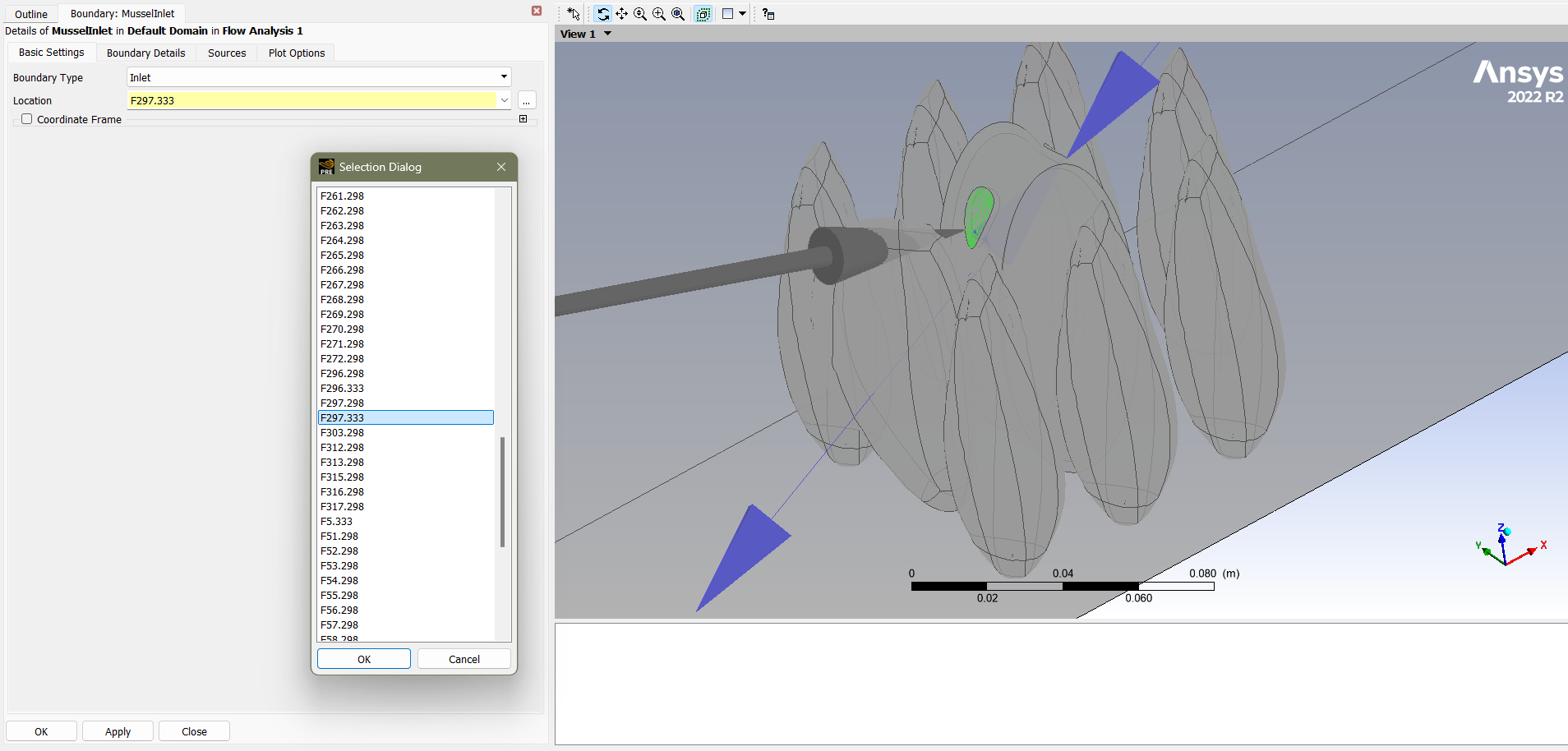
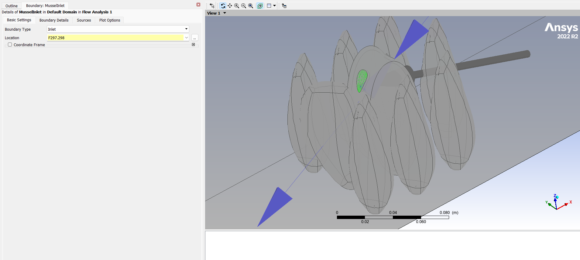
Thank you for that response. I am trying to place walls only on those faces I want to block off and create an inlet and outlet for the geometry which has an internal fluid volume, however I am having an issue where on the inlet and outlet faces, two faces are created and I do not know how to set the conditions for the secondary face created (.298 versus .333)
-
-
November 4, 2024 at 4:11 pm
Mark O
Ansys EmployeeHi, you do not create inlets or outlets on internal faces. Inlets/outlets are boundary conditions. They can only exist on faces that have no volume mesh on the exterior side. The internal faces are just either connected mesh regions or walls.
-
November 4, 2024 at 4:22 pm
Kelsey O'Donnell
SubscriberHi Mark,
To clarify, are the internal faces in this case the ones with a different code (.333) than the rest of the faces? Originally it was set as a wall however I didn't think this made sense to have the outer face set as an inlet/opening and the inner face set as a wall as I assumed that would cause an error? What I have currently set is the face highlighted in the above photo as the inlet and the opposite face (where the blue arrow is) as the outlet and all other faces as a non-slip wall. I am a bit unsure on what I should be setting these boundary conditions to instead.
-
-
November 4, 2024 at 4:24 pm
-
November 4, 2024 at 4:31 pm
Mark O
Ansys EmployeeIf your internal region is entirely surrounded by faces with a mix of walls, inlets and outets then you will still get an isolated region error because nothing that is happening outside will have any effect on what is happening inside.What is the driver of the flow through the mussel? If it is coming from the external flow solution then there is nothing to do except not set walls on faces you want the flow to pass through.If the flow being driven through the mussel is not coming from the external boundary conditions but something internal to the mussel, then you have two options(1) Do not mesh the mussel. The inlet to the (non-meshed) mussel region is an outlet for the exterior region with a specified mass flow. The outlet from the (non-meshed) mussel is an inlet to the exterior region with the same mass flow.(2) mesh the mussel region and add a momentum source somewhere inside the mussel region that is simulating whatever it is that is driving the flow through the mussel.-
November 4, 2024 at 6:57 pm
Kelsey O'Donnell
SubscriberHi mark,
Thank you so much, this is incredibly helpful! A few follow up questions. First, by do not mesh the mussel do you mean the "solid" geometry or the internal volume or both? Second, if I chose the third option I am not sure how one is to mesh only certain faces (the inlet/outlets as you say)?
-
-
November 4, 2024 at 5:04 pm
Mark O
Ansys EmployeePS. Another option is to not mesh the outside and just mesh the mussel with its inlets an outlets. Ultimately you have to decide what it is about the flow solution that you want to solve for and what it is that you know in advance about where and how much is coming in or going out and that will decide where to place the boundaries.
-
November 5, 2024 at 9:27 am
Mark O
Ansys EmployeeHi, I mean both the internal volume and the physical solid volume. In Ansys meshing there will be some number of geometrical solids that have been read in that may or may not be in the same part. Ansys meshing meshes each part separately so only solids in the same part have a connected mesh. The mesher doesn't care whether those regions will later be assigtned to be a fluid region or a conducting solid region later on in CFX-Pre. You are free to tell Ansys meshing not to mesh a particular soild by suppressing it. So you do not have to mesh every solid that has been read in to Ansys meshing. You could even defer this decision to CFX-Pre by only creating domains for just some of the mesh objects that it has read in.
-
- You must be logged in to reply to this topic.


-
5044
-
1749
-
1387
-
1248
-
1021

© 2026 Copyright ANSYS, Inc. All rights reserved.

