TAGGED: photonics, ring, ring-resonators
-
-
October 29, 2024 at 9:55 am
abhishek_2311ee20
SubscriberDear Ansys Support Team,
I am Abhishek Kumar Anand, currently an MTech student in Communication Systems and Signal Processing at IIT Patna. I am working on a simulation project involving the Optical_Ring_Modulator.icp in Ansys Electronics Desktop, which is currently set for a wavelength of 1310 nm. However, I need to adjust this simulation to operate at 1550 nm.
I would greatly appreciate guidance on making the necessary adjustments to accommodate this wavelength change. Specifically, I am looking for advice on any modifications required for the
neff_vs_voltage_11.txtfile, and adjustments to the ring modulator’s physical parameters, such as length and radius, to ensure accurate simulation results at 1550 nm.Thank you very much for your assistance and insights. I look forward to your response.
Best regards,
Abhishek Kumar Anand
MTech Student, Communication Systems and Signal Processing
IIT Patna
abhishek12.09anand@gmail.com -
December 4, 2024 at 3:24 am
GWANG
Ansys EmployeeHi Abhishek,
Thank you for the post. To change the system to work at 1550 nm, we can use these two examples as the start point:
Component level ring modulator simulations: https://optics.ansys.com/hc/en-us/articles/360042322794-Ring-Modulator
Build ring modulator reduced-order model and use it in PIC designs: https://optics.ansys.com/hc/en-us/articles/360042329094-Ring-modulator-time-domain-INTERCONNECT
In the first example, we will need to re-run the simulations with the wavelength update to 1550 nm, and that will generate us the file "neff_vs_voltage.txt". You can follow the exact steps to re-run the simulations but just change the simulation wavelength to 1550 nm. Then will all the files generated, you can import the files to the reduced-order model in the second example. You can follow the first step in the second example to test and find the best working length and radius for the ring modulator model for the desired modulation depth. Then you can use the model in PIC designs and simulations.
Please give this a try and let me know if you see any problems.
-
December 4, 2024 at 8:52 am
abhishek_2311ee20
SubscriberDear Ansys Support Team,
Thank you for the detailed explanation and the helpful links. I will follow the steps you’ve outlined to re-run the simulations at 1550 nm and generate the "neff_vs_voltage.txt" file. Once that is done, I will proceed with the reduced-order model as you suggested.
However, I am not very familiar with designing circuits involving photonic devices. Could I kindly request the Ansys team to assist with designing a circuit that uses the ring modulator for light modulation? Specifically, I need help incorporating a voltage waveform from a PWL source file to drive the modulator.
Your guidance or a ready example for this would be immensely helpful. Please let me know if this is possible.
Best regards,
Abhishek Kumar Anand
MTech Student, Communication Systems and Signal Processing
IIT Patna
abhishek12.09anand@gmail.com -
December 4, 2024 at 8:56 am
abhishek_2311ee20
SubscriberDear Ansys Support Team,
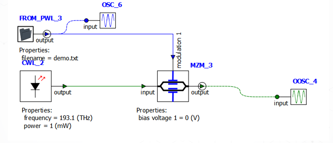
I am attaching a circuit I have been working on where I successfully modulated light using a Mach-Zehnder modulator. My goal is to achieve the same task using a ring modulator. Since I am not very familiar with the design specifics for this task, I would like to request assistance from the Ansys team in designing the circuit for the ring modulator. The circuit should incorporate a voltage waveform from a PWL source file to drive the modulation.
Your assistance in adapting my current setup for the ring modulator would be greatly appreciated. Please let me know how to proceed or if you need additional information.
Best regards,
Abhishek Kumar Anand
MTech Student, Communication Systems and Signal Processing
IIT Patna
abhishek12.09anand@gmail.com
-
December 9, 2024 at 9:15 pm
GWANG
Ansys EmployeeHi Abhishek,
That sounds good. The circuit design should be based on your design purposes. Could you please let me know what do you plan to use the ring modulator for? And let me know if you have any reference paper. If you just want to test the ring modulator itself, the time domain example online page has a testbentch for it.
-
December 10, 2024 at 5:20 am
abhishek_2311ee20
SubscriberDear Gwang,
I hope this email finds you well. I am currently working on a project involving the modulation of a laser signal using a ring modulator. The objective is to utilize a voltage waveform provided via a PWL (Piece-Wise Linear) file to modulate the laser output.
The specific requirements for this setup are as follows:
- The input voltage waveform, described in the PWL file, should be used as the control signal for the ring modulator.
- The ring modulator should appropriately modulate the laser signal (intensity, phase, or frequency) according to the PWL voltage waveform.
- The output of the system should reflect the modulation pattern dictated by the input voltage.
Additionally, I would be immensely grateful if you could provide a circuit design for this system and share the corresponding ICP file. Having this would significantly aid in the implementation of the project.
I would appreciate any guidance, resources, or suggestions on implementing this setup effectively. Please let me know if there are specific tools, software, or experimental setups that you recommend for simulating or realizing this configuration.
Thank you for your time and assistance. I look forward to your response.
-
December 19, 2024 at 9:32 pm
GWANG
Ansys EmployeeHi Abhishek,
The example file provided in this article is almost the one you described: https://optics.ansys.com/hc/en-us/articles/360042329094-Ring-modulator-time-domain-INTERCONNECT. Please use this as a start point, and let me know if you see any problems modifying the files.
-
- You must be logged in to reply to this topic.


-
4512
-
1494
-
1386
-
1209
-
1021

© 2025 Copyright ANSYS, Inc. All rights reserved.


