TAGGED: Ansys Discovery, static-structural
-
-
October 28, 2024 at 8:09 am
ahmed.aliyu
SubscriberHello ANSYS Community,
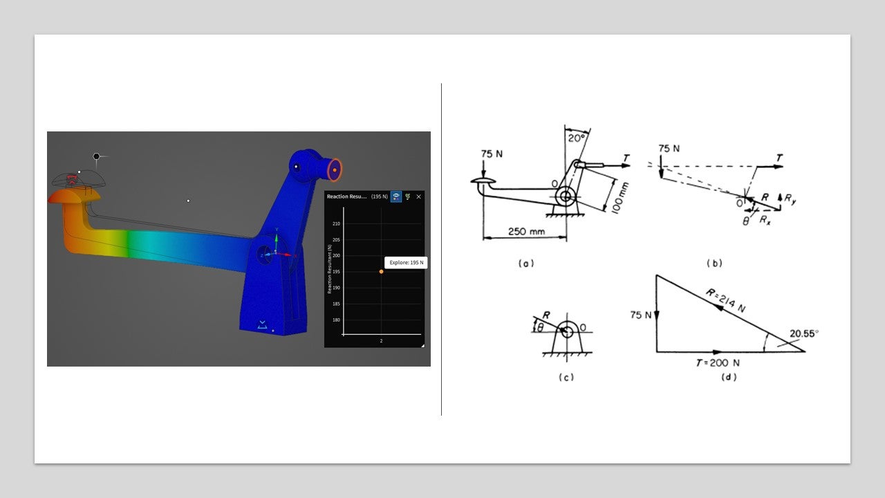
I'm working on replicating a mechanical engineering textbook example of a Motorcycle footbrake using ANSYS Discovery for validation. The problem is as follows:
A motorcycle footbrake lever (see attached image) is pivoted at O. With a 75 N vertical force applied by the rider’s foot, determine the tension T in the horizontal connecting cable and the reaction at point O.
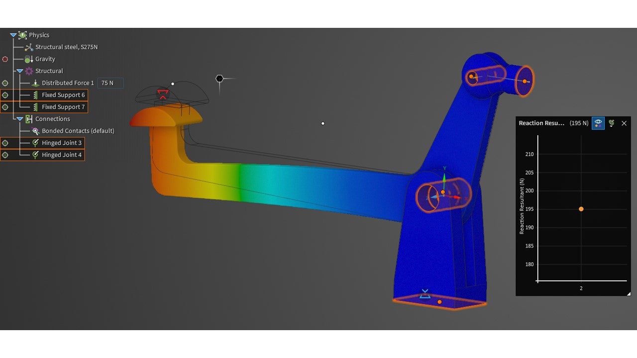
I've carefully followed the problem setup as per the book’s parameters (including key geometry and load applications), but my results (195N) differ slightly from the expected values provided in the text (200N). The discrepancy is within a 2.5% margin of error.
Could someone help clarify if this level of error is generally acceptable for typical ANSYS simulations, or might there be a specific setting or factor I should adjust to achieve even closer alignment? Any insights into common sources of minor deviations when replicating textbook examples would be appreciated!
Thank you!
-
October 28, 2024 at 12:40 pm
ErKo
Ansys EmployeeHi
Think within eng. accu., 2-5 % is pretty ok perhaps
Still see if the below gets it lower :
use the fidelity in the explore tabe at the bottom of the Discovery window.
See her for more on that (fidelity in explore mode):
https://innovationspace.ansys.com/knowledge/forums/topic/understanding-fidelity-in-explore-mode/
All the best
Erik
-
October 28, 2024 at 1:37 pm
ahmed.aliyu
SubscriberHi Erik,
Thanks for the very quick response.
I cranked up the fidelity to the highest resolution (0.34mm)
It did not make a difference to the value of the resultant. I even experimented by applying a Torque equivalent to the applied load still no difference.
I understand and appreciate that everything falls within a margin of error (Simulation or real case). For example, in the real world, the load would not be applied centrally or distributed evenly etc.
By removing the anchor/ground fixed support and applying a Fixed Hinge support at the point of rotation, the solution improved to 198N. Very good indeed.
The resultant at point O is at 213N.
The other question I have for you is?
Is there a way to find the vector or direction of this value? From my earlier post, there is a 20.55 deg vector on this resultant reaction force.
-
- You must be logged in to reply to this topic.


-
4618
-
1530
-
1386
-
1210
-
1021

© 2025 Copyright ANSYS, Inc. All rights reserved.


