Ansys Learning Forum › Forums › Discuss Simulation › General Mechanical › Coupled field transient of brakedrum › Reply To: Coupled field transient of brakedrum
Hello Peter,
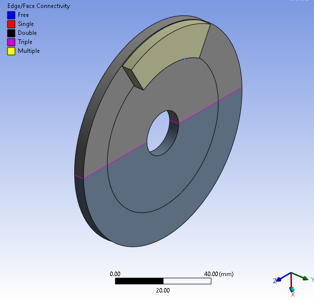
I had previously made the geometry from drum brake context. I’ve recreated the model as you mentioned shown below,
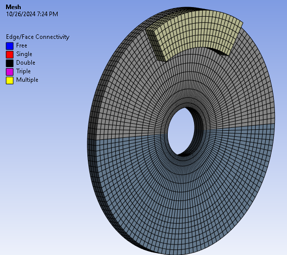
Mesh with 4 elements across thickness-
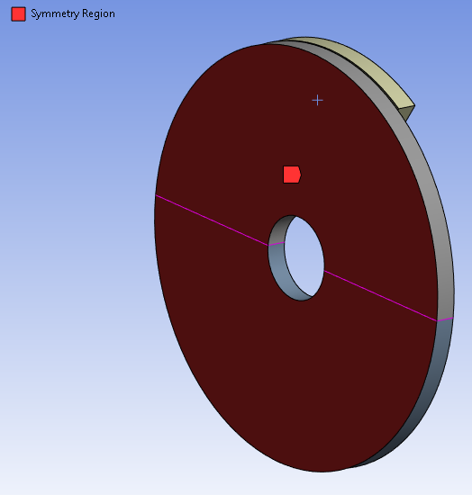
Symmetry region created. Any corrections required here?
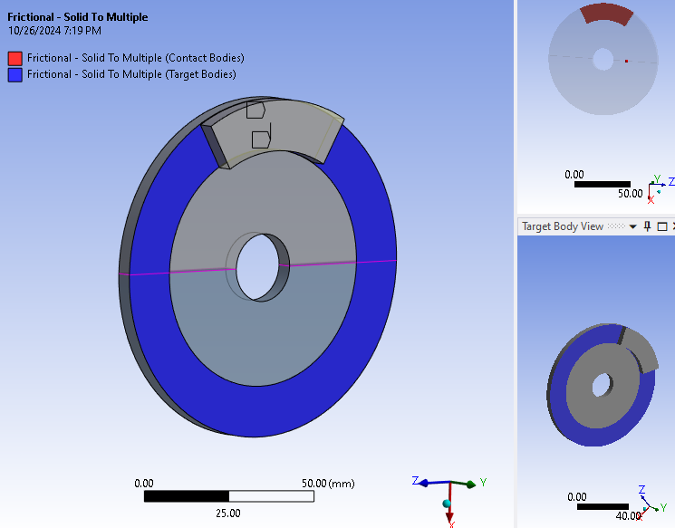
Frictional contact given-
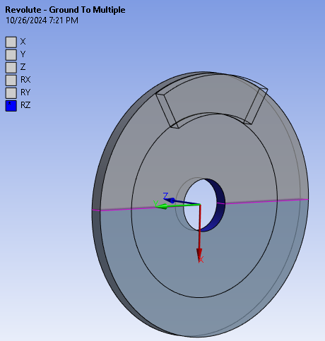
Revolute joint-
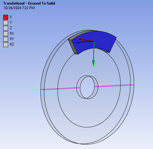
Translational joint-
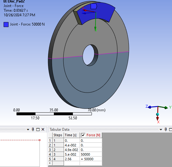
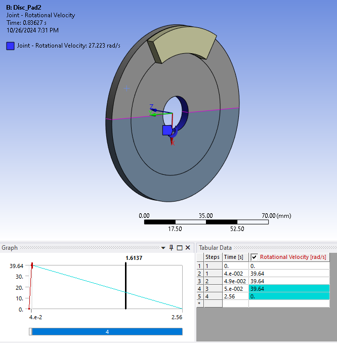
Joint loads- Force & Rot. Vel.-
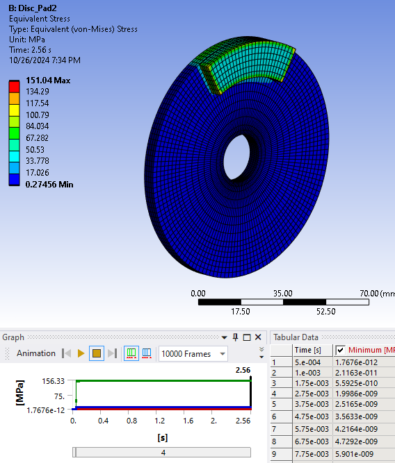
Equivalent Stress- Max. occurs in pad-
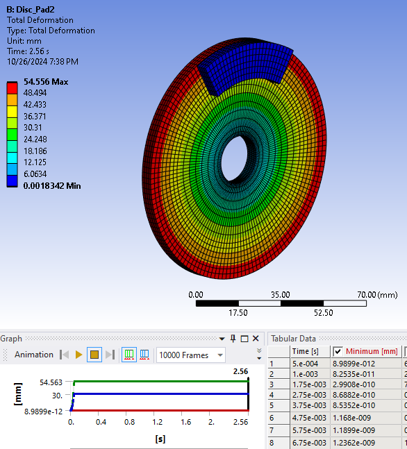
Total deformation- Max occurs in disc-
The stress and deformation is seen to be constant after joint force application.
In one of your previous posts, you had mentioned the method to apply the rotational velocity as joint load the link is mentioned below-
https://www.google.com/url?sa=t&source=web&rct=j&opi=89978449&url=https://innovationspace.ansys.com/forum/forums/topic/initial-angular-velocity-in-transient-structural/&ved=2ahUKEwi1-fj-o6yJAxWRT2wGHTR5KG0QFnoECCQQAQ&usg=AOvVaw0eMNi-CudqpMyj76-OaYio
I’ve followed the steps mentioned in the above post and applied the joint load rot. vel. so as to get a free rotation at 0.05s , but I don’t see the disc gradually coming to a stop at the end of 2.56s when brake force is applied at 0.05s. In the above image for rotational velocity, I’ve deactivated the steps for 0.05s and 2.56s in order to get a free rotation. Should I make any changes to the applied load?
I am trying to achieve that free rotation, but after brake force at 0.05s, the disc stops suddenly. I've observed this same case while performing the coupled field transient for brakedrum mentioned in the previous discussion.
I would like to know your suggestions regarding how I can use this simulation physics of disc brake and implement it for drum brake simulation.
Regards,
Rohan.
