-
-
October 25, 2024 at 3:12 pm
Can Ozturk
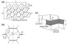
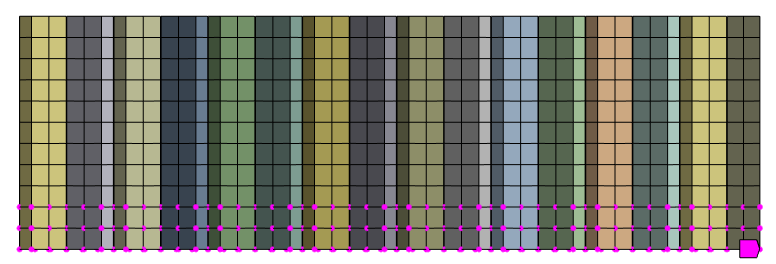
SubscriberI am trying to find the Shear Properties (modulus) of the honeycomb core material in the ribbon (L) direction. For this, I simulated the ASTM 273 test and tried to obtain the core shear modulus included in Hexcel's TDS, this tds includes the dimensions of the test sample and the strain rate speed. I drew the walls of the honeycomb geometry as a midplane by taking into account the cell size, foil thickness, t 2t etc. and additionally defined bonded contact in the places where the walls touch each other (becomes 2t). Btw my mesh quality is almost perfect. It is written in the technical data sheet that the material is 5052 aluminum, I took these properties from MMPDS. Despite all this, the modulus I calculated as a result of my analysis is 239 MPa, while this value is 344 MPa in TDS. Why is this difference?Even if I reflect the geometry exactly and include the fact that the material is isotropic 5052 aluminum and simulate ASTM 273 with the same sample size, I get a very different value than the shear modulus found in TDS. Can you help me with this issue?Peternewozman? -
October 26, 2024 at 12:45 am
peteroznewman
SubscriberHexcel provides the shear properties in their datasheet that were measured on their product so structural analysts can use them to build simulations of that honeycomb core in structural models that have a honeycomb core sandwich panel.
Most analysts will take the three modulus values in the three directions and create an orthotropic material model that can be applied to a solid body that represents the core. That solid body can be meshed with solid elements. To turn that into a structural sandwich panel, facesheets are required. If these are aluminum facesheets, these could be modeled as shell elements on a surface that is on the top and bottom faces of the solid core, or the facesheets can be modeled using solid elements meshed on a thin solid that is on the top and bottom faces of the solid core. In either case, Shared Topology is used to connect the facesheets to the core.
I see you are trying to simulate the shear test of the product. One source of error between your model and the physical test is the adhesive that bonds the core to the facesheet or test plates. This adhesive has some thickness and during bonding, the edges of the walls sink into that thickness and the adhesive climbs up the walls creating a fillet and shortening the effective dimension of the thickness of the core. This will result in a higher modulus than your model which does not include the support of the adhesive.
-
October 26, 2024 at 5:42 am
Can Ozturk
SubscriberMy sample is 1/4 – 5052 – .0015. ASTM 273 has two option for specimen and these are core with facesheet or without facesheet. This is the TDS document and on page 13 there is information about the test, that is, the sample was tested without a facesheet, so the sample is directly connected to the test plate.
I thought about what you said about adhesive, but does this difference affect the shear modulus by almost 100 MPa? Then can't it be modeled at all because of adhesive, hc? Because unless you use the orthotropic material properties in tds, it will give wrong results. Isn't the geometry that gives the honeycomb core its shear properties the main factor?
-
October 26, 2024 at 11:32 am
peteroznewman
SubscriberHoneycomb core is made by bonding sheets of foil and expanding them.
Another source of error is the presence of an adhesive material between the foil sheets which has a much lower modulus than aluminum.
Your model uses bonded contact to connect the foil sheets to make the 2t thickness instead of adhesive, so your model has a higher modulus than the physical product.
-
October 26, 2024 at 12:16 pm
Can Ozturk
SubscriberSo if my model has a higher modulus than the physical product, then if there were two products in real life (a core with adhesive and a core with higher stiffness due to bonded contact) and we applied the same shear force to them, wouldn't the core with bonded contact, which is stiffer, make less displacement? Or in other words, wouldn't the core with bonded contact have more reaction force for them to make the same displacement? I think the answers to these questions are yes.So shouldn't I find the shear modulus of the core with bonded contact higher than the product with adhesive? Because in ASTM 273, as the slope of force deflection increases, the shear modulus increases and the remaining parameters in the formula are related to the sample size. -
October 26, 2024 at 2:15 pm
peteroznewman
SubscriberBonded contact is a simulation object you may have used in your model to connect the foil. You mentioned that your model uses bonded contact. Maybe that was only to connect the edges of the core to the face of the test plate and you created the 2t effect on the shell model by entering twice the thickness on the shell. You could have used bonded contact between two shell elements each of thickness t. In either case, the model does not have a low modulus adhesive layer between the foil layers that are found in the physical product.
A stiffer connection between the foil in the model would result in a higher shear modulus, but this may only be a tiny effect due to the very thin layer of adhesive, while the first error I mentioned of the adhesive in the product could be a huge effect by comparison and this goes in the opposite direction, making the product stiffer than your model.
Another source of error in the model for the measured shear modulus is the formulation for the bonded contact between the edges of the core and the face of the test plate. Some bonded contact formulations connect the edges to the face using what you can think of as springs. These springs are automatically calculated in the solver. Those springs will reduce the modulus you measure compared with other formulations that don't use springs.
-
October 26, 2024 at 3:35 pm
Can Ozturk
SubscriberI have used bonded contact between two shell elements each of thickness t. and for this part "Another source of error in the model for the measured shear modulus is the formulation for the bonded contact between the edges of the core and the face of the test plate. Some bonded contact formulations connect the edges to the face using what you can think of as springs. These springs are automatically calculated in the solver. Those springs will reduce the modulus you measure compared with other formulations that don't use springs.", I have used fixed joint between top and bottom of core edges and test setup plates with pinball region which is so small since my mesh size alsa so small.
-
October 26, 2024 at 7:03 pm
peteroznewman
SubscriberFixed Joints could be a problem, they behave differently to Bonded Contact. Fixed Joints can be defined with the Behavior set to Rigid or Deformable. I believe the default is Rigid. Check to see what you have used and reply with the setting used.
After the model has solved, you can visualize the constraint equations the Rigid Fixed Joints created. Click on the Solution Information folder in the outline, the graphics window switches to the Worksheet tab at the bottom. Click on the Geometry tab at the bottom of the graphics window and you should see the red spider legs of the contraint equations representing the Fixed Joint. Reply with a screen image of that.
Fixed Joints are different to Bonded Contact. Fixed joints take all the nodes on the reference side and connect them to one node at the center, and do the same for the mobile side so all the forces and moments are transfered through that pair of nodes at the center. If you have a Rigid Fixed Joint, then none of the nodes can move out of the plane they start in, meaning that the test plate cannot flex. This may be okay since the test plate is supposed to be much stiffer than a typical thin facesheet, but if you were modeling a thin facesheet, using a Fixed Joint to connect the edges at the top of the core to the top facesheet would be a huge mistake. Bonded contact acts locally, so the facesheet can flex due to the applied loads.
Bonded contacts also have a Pinball radius and that would be one way to represent the effect of the adhesive supporting the cell wall for some height above the test plate. You can do some testing with progressively larger values of Pinball radius and plot the curve of Shear Modulus vs Pinball radius.
Bonded contacts have several formulations. You are using Bonded Contact for the cell wall to cell wall bond to create the 2t wall. One formulation that does not use “springs” to connect the two sides is MPC which is the default unless the model has an exclusion that causes it to use the Augmented Lagrange, which does use “springs”. A Rigid Joint may be an example of an exclusion.
The preferred way to connect the edges of the core to the test plates and the cell walls to each other to get 2t is to use Shared Topology in SpaceClaim and delete all the contacts and joints.
You haven’t described how you are supporting and loading the test plates to solve the model to obtain the shear modulus.
-
October 26, 2024 at 10:08 pm
Can Ozturk
SubscriberThank you very much for taking the time to help me. First thing tomorrow morning, I will try to explain my model more clearly with screenshots.
-
October 27, 2024 at 8:01 am
Can Ozturk
SubscriberNe yazık ki remote olarak ağda bir sıkıntı olduğundan ayın 30una kadar ulaşamayacağım modele ama detayları paylaşmak isterim. Bonded contact kullandığımda core edge ile plate'in orta kısımları birbirlerini tutmaktaydı bende her şey program controlled'teyken. Bende bu nedenle fixed joint kullanmaya karar verdim. Modelimde facesheet yok ve Testin gerçekleşme mantığını düşündüğüm zaman jointlerin rigit olmasını gerektiğini düşündüm.I supported my model with fixed support from bottom face of bottom plate(bottom and top plates are solid) then between top face of bottom plate and bottom edge of core fixed joint, then bonded contact between walls of core, then between top edges of core and bottom face of top plate I have fixed joint.The ASTM document states that the load to be applied should cut the core diagonally. For this reason, I applied the force and displacement that I applied to the top plate by assigning a coordinate system. In addition, I wondered if there would be a difference if I applied it parallel to the plate and tried that too and observed a difference of 1 mpa in modulus, so it is not very effective.In addition, when I applied 500 N (it is a random number because I only need the slope in the linear region of the force displacement curve) and solved linearly, the modulus I obtained is 239 MPA, and when I only turned on the large deflection in the same model, the modulus is 212 MPa. Later, the strain rate was given as 0.0020 inc/min in Hexcel TDS, and I applied displacement in this way and solved linearly, which I thought would be more accurate, and found the shear modulus to be 242 Mpa. Afterwards, when I turned on the large deflection in the same model, the modulus was around 220 MPa. I applied displacement in 10 steps and in the 10th step, the end time was 60 seconds. -
October 27, 2024 at 11:25 am
peteroznewman
SubscriberI used Google Translate on your first paragraph to read the following:
Unfortunately, I will not be able to reach the model until the 30th of the month due to a problem with the network remotely, but I would like to share the details. When I used bonded contact, the middle parts of the core edge and plate were holding each other when everything was in program controlled. That's why I decided to use a fixed joint. There is no facesheet in my model and when I thought about the logic of the test, I thought the joints should be rigid.
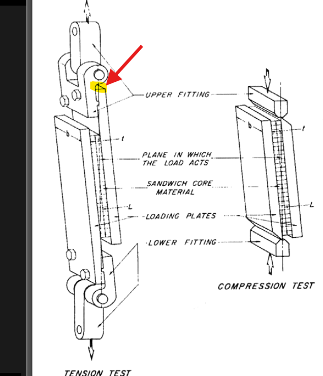
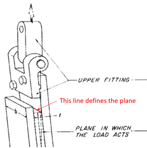
I agree that the load travels diagonally through the core, so it is good to have a Csys that creates the diagonal plane. The force on the top test plate should be applied in a coordinate direction of that Csys. What face of the top test plate did you select to apply the force to? In the figure above, the end face near the pivot pin would be a good selection if the centroid of that face lies on the diagonal plane. If the centroid of that face is not on the diagonal plane, then you should use a Remote Force and set the coordiantes of the remote point to be on the diagonal plane by using the diagonal Csys and typing in a zero on the axis normal to the plane.
If the bottom side of the core has a Fixed Support, there is no need for any displacement boundary condition on the top test plate, there should only be a force. Please clarify what displacement you are applying to the top plate.
I also agree that the test plates are much stiffer than the core so treating them as perfectly rigid will not alter the results too much.
I agree that you want the initial slope of the shear deformation, so a linear solution is all you need. Don't bother to turn on large deflection, you are not interested in the nonlinear response. In a linear solution (large deflection off), the load can be an arbitrary number like 500 N or 1 N since you are simply creating a ratio. In a linear solution, time is irrelevant, the End Time is usually 1 second. In a Static Structural, the strain rate is irrelevant. In a linear solution, you only need 1 step to solve. Again, what displacement are you applying?
To get a Modulus, you either apply a force and measure the displacement, or you apply a displacement and measure the reaction force. If you are applying a force, there should be no applied displacement, only a directional deformation value of the remote point where the force was applied.
-
October 27, 2024 at 12:36 pm
Can Ozturk
Subscriberı applied force from this surface and ı split this face with line and also ı did same to bottom plate then ı created plane then ı used this plane for creating coordinate system and also ı used remote force. so this part seems ok ı guess.
As I said before, I thought about whether it would be more correct to apply displacement or force on the model and as I mentioned above, I created 2 different models. In the first model, I obtained 239 mpa (force was applied), in the second model, I applied displacement and obtained 242 mpa (it says the tests were performed with 0.0020 inch/min, so I applied 0.0020 inch). In order to see the difference between them and I observed that it did not make a big difference. What I am trying to explain is that I did not apply two things to the model at the same time. In order to observe the difference, I applied force and displacement separately.I used directional deformation while calculating shear modulus. Also, I checked the force reaction and of course I got what I applied. -
October 27, 2024 at 12:38 pm
Can Ozturk
Subscriberphoto that ı tried to upload doesn't work so ı try to explain, force that ı applied the end face near the pivot of plate.
-
October 27, 2024 at 1:28 pm
peteroznewman
SubscriberTo insert an image, do a screen capture using Snipping Tool then click in your reply and Paste.
If you mean you split the large bottom face of the top plate at the line where the honeycomb core begins, that would be the correct way to define one line on the plane. The same for the other end at the top face of the bottom plate where the core begins.
If you use a linear model and apply the force or displacement at the same location in the same direction, the modulus will be the same value whether you calculate it from the displacement input or the force input.
-
October 27, 2024 at 1:49 pm
-
October 27, 2024 at 1:56 pm
Can Ozturk
SubscriberIn light of what we talked about the analysis model, I see that the model setup and assumptions I made match with yours. But the modulus is 100 MPa different as a result. Could you please review the model if I add it here on Wednesday? Maybe I'm missing something. I set up the model in ansys 2020 r1. But if there is a version problem, I can only add the geometry and share screenshots of my setups here.
-
October 27, 2024 at 2:06 pm
peteroznewman
SubscriberThe same line on the opposite end of the core on the opposite test plate completes the definition of the plane. Depending on how long the overhang on your test plate is, the center of that face may or may not lie on that plane.
Yes, I can open an Ansys 2020 R1 model to look at it, make sure to use File Archive and create a .wbpz file. Provide a link to that file from your Google Drive or OneDrive in your reply.
-
October 27, 2024 at 2:16 pm
Can Ozturk
SubscriberThank you so much again! I'll share it as archive file.
-
October 30, 2024 at 7:13 am
-
October 30, 2024 at 12:31 pm
peteroznewman
SubscriberHello, I have your archive. Please reply with the area you used to compute the shear modulus.
-
October 30, 2024 at 12:40 pm
-
October 30, 2024 at 7:38 pm
peteroznewman
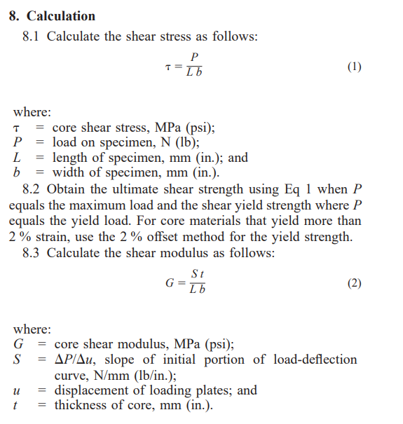
SubscriberThe area I was asking about is L b. What values did you use for L, b and t?
-
October 31, 2024 at 3:22 am
Can Ozturk
SubscriberL: 7.5 inç b: 2inch and t:0.625 inc, these values are given in hexcel the document.
-
October 31, 2024 at 11:59 am
peteroznewman
SubscriberThe honeycomb core in your model measures L = 7.417, b= 1.985 t=0.626 so you should use that in the calculation.
Using the load of 112.4 lbf gives a shear stress of 7.634 psi.
I simplified your model and got a displacement of 1.2832e-004 in so S = 875935
Shear Modulus of 37244 psi or 256 MPa.
I made a Nodal Named Selection called Shorter Base that I used as a Fixed Support to simulate the shortening of the unsupported core caused by the adhesive fillet.
That reduced the deformation to 1.0588e-004 in so S became 1.062e+6
Shear Modulus of 45137 psi or 311 MPa.
You can see that by adjusting the unsupported thickness of the core, the Shear Modulus can be tuned to the value published in the TDS.
-
October 31, 2024 at 1:01 pm
Can Ozturk
SubscriberThank you so much! Can you share your archive file please?
-
October 31, 2024 at 10:48 pm
peteroznewman
SubscriberI don't have Ansys 2020 R1 so I did the work in 2023 R1.
I can provide the archive but you won't be able to open it in 2020 R1.
-
November 1, 2024 at 5:53 am
Can Ozturk
SubscriberActually if you add it here I can open it at work. Also may I ask, I can't find the compression modulus and this was on workbench. I did it according to ASTM 365, and again I performed the test according to the sample dimensions in the hexcel tds, but the compression modulus of the Core was very different from the hexcel tds.
-
November 1, 2024 at 11:19 am
peteroznewman
SubscriberHere is the Ansys 2023 R1 archive of the Shear Test.
I didn't touch the Compression Test, I haven't read ASTM 365.
While it's interesting to see if you can simulate the test, I don't understand the practical use of this highly detailed model.
The point of Hexcel providing the Shear Modulus is so you can use it in an accurate simulation of the bending behavior of an aluminum honeycomb core sandwich by creating an orthotropic core material. As you found, the detailed model doesn't match the Hexcel data, so what is the practical use of this model?
-
November 1, 2024 at 12:37 pm
Can Ozturk
SubscriberWhen I calculated the Shear Modulus using the values you provided, I found it to be 45155.4 psi, which corresponds to 311 MPa. However, you indicated it as 617 MPa. Could there be a mistake in your calculation?
The values I used are: L = 7.417, b = 1.985, t = 0.626, S = 1.062e+6.
-
November 1, 2024 at 5:22 pm
peteroznewman
SubscriberYes, the correct value is 311 MPa. I updated the earlier reply.
-
- You must be logged in to reply to this topic.


-
4833
-
1587
-
1386
-
1242
-
1021

© 2026 Copyright ANSYS, Inc. All rights reserved.


