Hi!
I have been trying to model the cracks with the function PLCRACK and solid65 elements in Ansys Workbench 19.1. I am modeling a concrete cilinder which excist of two different materials. The contact area between these two materials is bonded. I modeled a quater of this cilinder and used symmetry (cyclic region) to model the whole column.
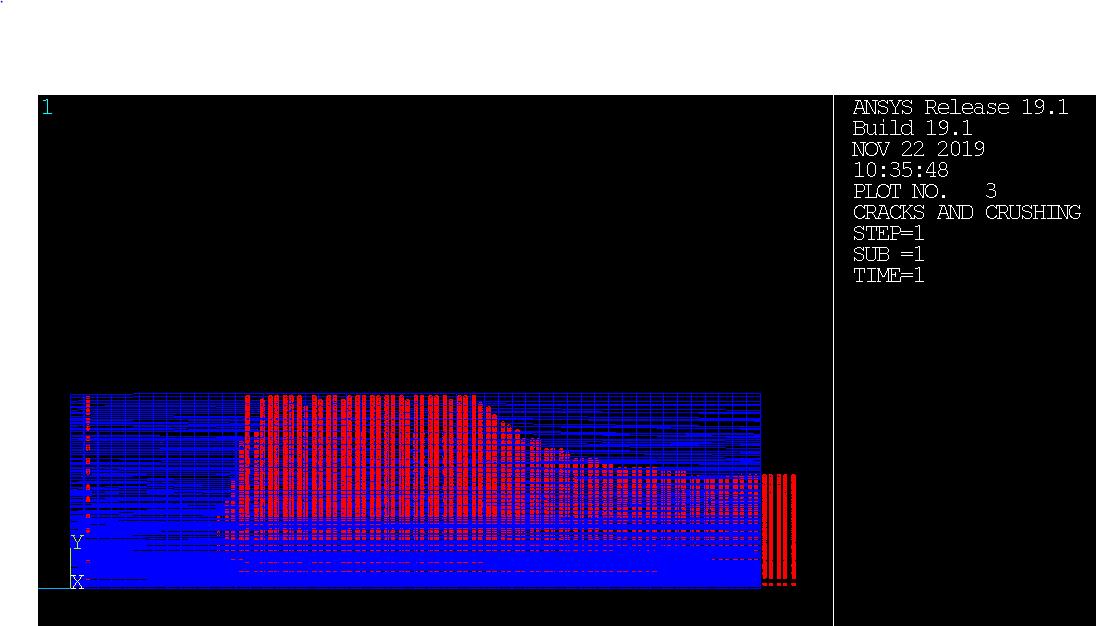
Right now it is possible to see the cracks, which are shown by small circles. (see the picture) This is great, but I have the feeling that something is wrong with this crack pattern, that is why I have two questions:
1) To model the solid 65 element you need to add the stress-strain properties to the command section. I did this for both the materials, but only for compression. The cracking is based on the tensile strength. Do I have to add this to in the command section, or is the tensile ulitmate strength retreived from the "engineering data - materials" which are defined before?
2) How is it possible that red 'cracking' is shown on parts where no material excists? (see picture)
I added the model with this post for more information. I hope someone can help me! Thanks