TAGGED: macros/scripting, mechanical, postprocessing, python-scripting
-
-
October 22, 2024 at 3:00 pm
roshan.rajakrishnan
SubscriberHello,
I am performing some inelastic simulation of a component which involves several cycles of loading. To apply some design rules, I am trying to use Python scripting to extract the stress and strain data from nodes defined under a NamedSelection. Data from a chosen cycle is used for the creep fatige assessment (ASME/RCC-MRx).
I am learning to Python scripting in ANSYS and find it hard to perform this task. So far, I have extracted data from each node which I combine in a chart and export the chart data (Time, Steps, Substeps, Stress, Strain) to a csv file, from which I take the data for a desired cycle. As this method is not suitable for a large geometry, I want to know if the nodal solution can be limited to specific steps in the stress/strain objects. Or, if there is an efficient way to do this, please let me know.
-
October 24, 2024 at 10:33 am
Debanjan Debnath
Ansys EmployeeHello,
To extract nodal stress or strain results for specific nodes at a particular time step, the most efficient approach is to access the results directly from the result file. Using ExtAPI.Tools.GetResultsDataFromFile(result_file) can be particularly useful for this purpose. For more detailed guidance, you may refer to the Ansys Help documentation: Customization Suite → ACT Customization Guide for Mechanical → Mechanical Feature Creation → Post Processing Capabilities in Mechanical → Retrieving Mechanical Results More Efficiently.
Additionally, the Ansys Data Processing Framework (DPF) can also be utilized for this task. DPF allows for precise scoping of results to a specific time step and mesh, facilitating targeted analysis of simulation data. By leveraging DPF, you can efficiently access and manipulate the desired stress or strain values, streamlining the post-processing process.
Thank you.
-
October 30, 2024 at 1:42 pm
roshan.rajakrishnan
SubscriberThanks Debanjan for the recommendations. I have been practicing the examples from the ANSYS ACT Customization Guide for Mechanical (2019 R3). Particularly the code from 2.3.1.2. Defining Functions for the Custom Result (Von Mises Stress) has been very useful. I am interested in using "PRIN_S" option. While trying to validate the script results at a single corner node, I see some scatter in the results when compared to those given by user-defined results (S1,S2,S3). Mostly the differences are in the middle and minimum pricipal stresses. Later I found that the script results match the 'Average' data when 'Unaveraged' display option is chosen.
I am not able to understand the scatter between the data with Averaged and Unaveraged (min+max/2) results. Please inform if I have missed anything and inform about methods to achieve the same results as the Averaged data from ANSYS.
Additionally, I also interested in the middle nodes. But the PDF available online is missing some part of the code for defining the link table that provides the two corner nodes. Please let me know where this can be found.Thanks for your support.
-
November 6, 2024 at 8:10 pm
Debanjan Debnath
Ansys EmployeeHello,
Stress is initially calculated at the integration points within each element and subsequently interpolated to nodes through linear extrapolation. When multiple elements (e.g., three) share a node, each element provides an extrapolated stress value at that node (such as σ1, σ2, σ3), referred to as unaveraged stress. With the average display option enabled, the stress value shown at the node is the mean of these extrapolated values, calculated as: σ1 + σ2 + σ3 3 .
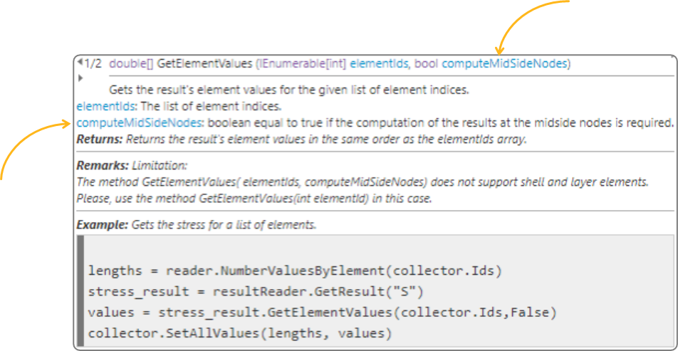
For midside nodes, you may be required to use input
computeMidSideNodes = Trueas shown in the figure below.The following sample script might be helpful. Where
ENSstores the elemental-nodal result.analysis = Model.Analyses[0]
reader = analysis.GetResultsData()
elem_id = 32
Sp = reader.GetResult('PRIN_S')
Sp.SelectComponents(['1'])
ENS = Sp.GetElementValues([elem_id], True)Thank you.
-
November 7, 2024 at 10:47 am
roshan.rajakrishnan
SubscriberThanks Debanjan. I will try the
computeMidSideNodesoption and get back to you.
-
- You must be logged in to reply to this topic.


-
4683
-
1565
-
1386
-
1242
-
1021

© 2025 Copyright ANSYS, Inc. All rights reserved.


