-
-
October 20, 2024 at 10:05 am
l76124262
SubscriberDear Technical Support Team,
I am currently working on the design of a ring modulator (MRM) and would like to modify an existing ring resonator as the base. Based on the examples provided on your official website, the design process mainly assumes a circular ring with uniform width, but my situation differs, so I am seeking your guidance.
Specifically, the inner ring of my ring resonator is not perfectly circular, and the width of the ring waveguide varies at different cross-sections, resulting in the effective refractive index (neffn_{\text{eff}}neff) changing with the position. Under these conditions, I have the following questions:
Simulation of Non-Uniform Width and Non-Circular Structure: Since the effective refractive index changes with the width of the waveguide, how should I accurately simulate such a non-standard geometry in Lumerical? Are there specific modules or methods suitable for handling such structures?
Impact of Doping on the Simulation: Due to the varying effective refractive index across different widths, I am unsure how to proceed with the doping simulation, especially considering how varying doping concentrations and refractive index changes at different positions may affect the overall simulation results.
Recommended Simulation Approach: For this non-standard ring modulator structure, do you have any recommended simulation workflows, mesh settings, or configurations to ensure accurate simulation of refractive index variations and the effects of doping?
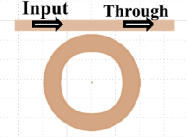
(Below is the structure of my ring resonator design by fdtd.)
Thank you very much for your assistance. I look forward to your advice and guidance.
Best regards
-
October 21, 2024 at 6:21 pm
Guilin Sun
Ansys EmployeeFor the non-regular ring, you may need to use several different polygons; of different number of partial rings depending on the change of the geometry. RIng object can have a start angle and stop angle. Or if you can draw it using other software, you can save it to an image and import it.
Doping will need to be simulated by CHARGE. Once the carrier distribution is obtained, you can import it ar charge attribute, which has some built-in carrier-index conversion mechanism: Charge distribution to change in refractive index theory – Ansys Optics
https://optics.ansys.com/hc/en-us/articles/360034901753-np-Density-and-Temperature-Index-Perturbation-Simulation-object
The workflow is similar to the standard ring with doping.
Please search online to find applicable examples as reference, and write a new post for each question new.
-
- You must be logged in to reply to this topic.


-
4683
-
1565
-
1386
-
1242
-
1021

© 2025 Copyright ANSYS, Inc. All rights reserved.


