-
-
October 17, 2024 at 4:05 pm
psaavedra2018
SubscriberHello everyone, I have a question about how HFSS works, and I hope someone can guide me.
I am working on the design of an OMT (Ortho-Mode Transducer) in a waveguide with a 200 MHz bandwidth, applied in radio astronomy, which must have the capability to measure HI and OH emissions.
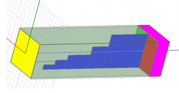
To achieve this, I am developing a design in HFSS 2020R2.4, where I am working with a waveguide that includes a stepped septum, which will allow the extraction of LHCP and RHCP. There isn't much information available regarding this type of polarization transformer or phase shifter. However, I am currently obtaining results and have noticed that, to calculate the phase differences between the two aforementioned ports, I am using the "Fields Calculator" in a volume. I have also seen some people using polylines to extract and measure the electric field.
I would like to know what is the most recommended approach when trying to analyze phases through the electric fields. My idea is to use these phase differences as objectives in the parametric analysis (90° deg and AR (Axial Ratio)).
Best regards!
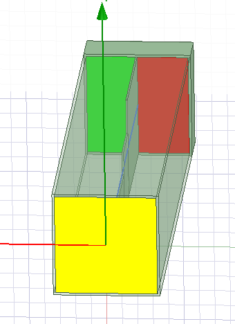
Green: RHCP (Mode 1 and 2: Not EXCITED)
Red: LHCP (Mode 1 and 2: Not EXCITED)
Note: Green & Red extracts diff phases.
Yellow: Excitation (Mode 1 and 2: 1W both, not phase diff)
Blue: Septum stepped (Link design: https://docs.google.com/spreadsheets/d/1HomUYZ_rmmzqgcdfzhH4d6WUUmURkmXs/edit?gid=1682293646#gid=1682293646)
-
October 31, 2024 at 11:55 pm
Irina G.
Ansys EmployeeHello,
as I understand, your design of OMT has 2 waveports on one side (green and red, one mode each) and yellow wavport with 2 alined (degenerate) modes on the other side. If you want to work with fiedls, it's better to add some kind of horn instead of yellow port and report LH and RH CP strength in Far Field wnen one of ports (green or red) On. Usually Axial ratio value is also important.
When keeping 3 ports, one need to create output variables as proxy to LH and RH circular polarized fields. For ideal circular polarization starting from green port, the conditions should be as follow:
mag(S(green, yellow1))=mag(S(green, yellow2)) and cang_deg(S(green, yellow1)) - cang_deg(S(green, yellow2)) = +/- 90deg. I would start with optimizing based on phase difference of S-parameters in the desired frequency band.
-
- You must be logged in to reply to this topic.


- Three-Phase Voltage Imbalances in dual stator electric generator
- Link the Circuit to 3D Terminals
- Magnetic Dipole moment calculation
- Integration lines or U Axis Line for circular and rectangular ports
- Core Loss in ANSYS MAXWELL Eddy Current solution
- exporting and importing my Netlist for my external circuit
- Error of Metal Fraction in Icepak Classic.
- The unit of theta in Is*sin(2*pi*fre*Time+theta-2*pi/3)
- 2D transient simulation -torque issue
- Two way coupling for Maxwell and thermal problem

-
4607
-
1515
-
1386
-
1209
-
1021

© 2025 Copyright ANSYS, Inc. All rights reserved.


