TAGGED: contact
-
-
October 17, 2024 at 5:47 am
JooJaehoon
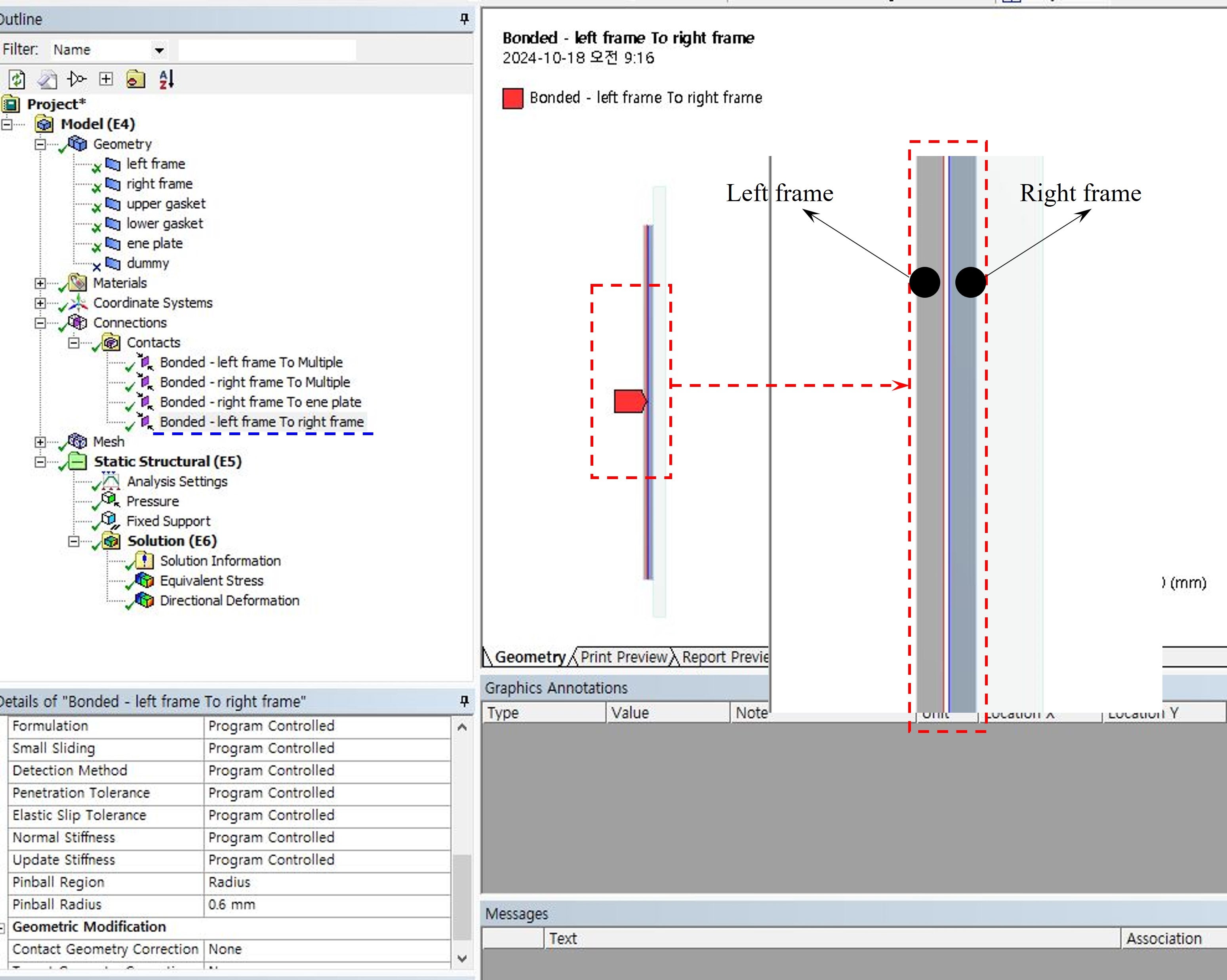
SubscriberHello !I'm conducting 2D structural analysis.I attached 2D shape as 1st pictureI set fixed support at left side and applied clamping pressure at right side.And, bonded condition is applied among all components.I intended to that right side defomed and finaly contacted at left side.but, I couldn't get I intended.First case, I'd set pinball radius automatically, then, got result (2nd, 3rd picture)Second case, I'd set pinball radius as 0.6 mm(component gap = 0.5 mm), the, got result(4th, 5th picture)How can I get intended result?regard -
October 17, 2024 at 8:26 am
tiwari15abhinav
SubscriberI recommend using bonded contact for the regions that are initially in contact. To achieve this, you can split the surface and ensure the component set is shared.
For the regions where contact is expected to occur from the right side to the left side during the simulation runtime, you should apply frictional or frictionless contact, depending on your specific case.
-
October 18, 2024 at 12:33 am
JooJaehoon
SubscriberI set bonded condition in all components.
I can't understand second sentence.
May I request more explain?
-
October 18, 2024 at 5:11 am
tiwari15abhinav
SubscriberIf contact occurs during the simulation runtime (i.e., at t=0, the left and right bodies are not initially in contact but come into contact due to the application of clamping pressure), you should use a nonlinear contact (either frictional or frictionless).
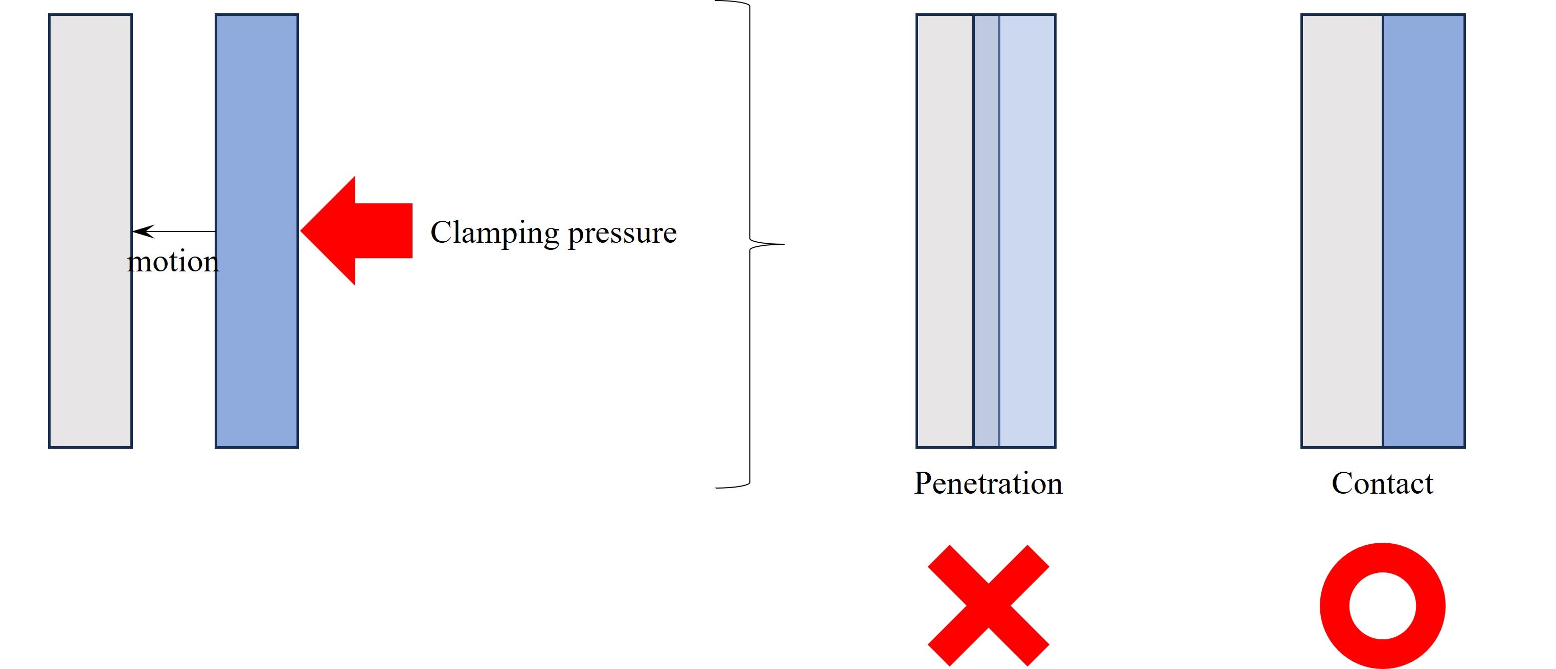
Based on the new image you recently added, it appears that the right body moves towards the left body due to clamping pressure, leading to contact. This scenario represents a case of nonlinear contact, where frictional or frictionless contact should be applied, as suggested by Mohan in the comment below.
-
October 18, 2024 at 5:34 am
JooJaehoon
SubscriberThank you for replying!
I'll try analysis again with nonlinear contact condition!
-
-
-
October 17, 2024 at 8:29 am
mohan.urs
Ansys EmployeeHey,
Sorry but I couldn’t understand what was your intended result. If possible can you explain it through a picture.
And another thing is you’ve expalined modifying contact pin ball radius settings, can you point out for which contact you have modified them, I do see that there is only one contact possible which is having a gap but i just want to confirm that and if you are usig bonded contact for that, that might be the issue. You can try using frictionless at first and then modify it to frictional when the results start making more sense to you.Thanks
-
October 18, 2024 at 12:36 am
JooJaehoon
SubscriberI attached 6th, 7th picture for your information.
I wish it help for your understand
-
-
- You must be logged in to reply to this topic.


-
4858
-
1587
-
1386
-
1242
-
1021

© 2026 Copyright ANSYS, Inc. All rights reserved.

.jpg)


