-
-
October 14, 2024 at 10:16 am
BALA
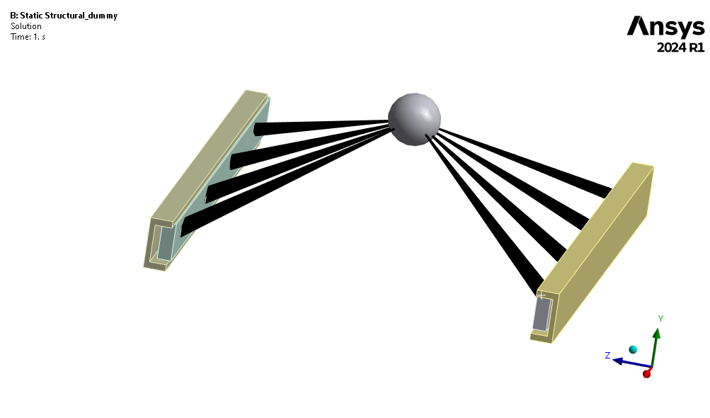
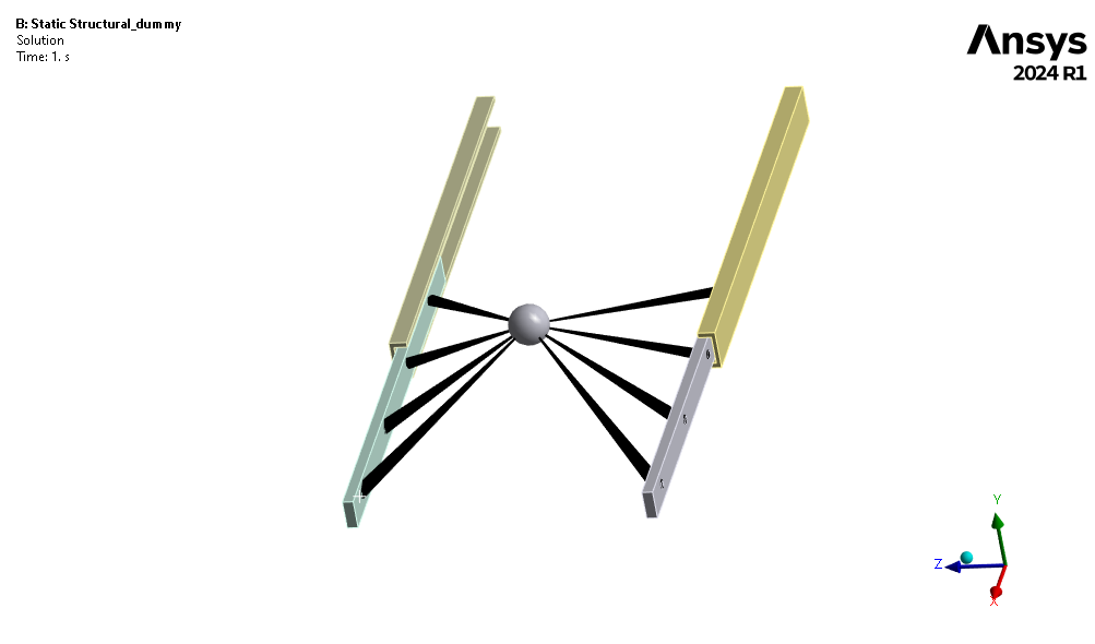
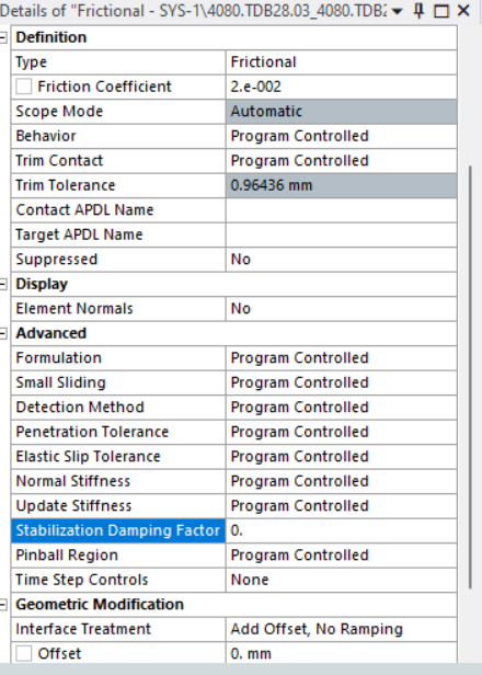
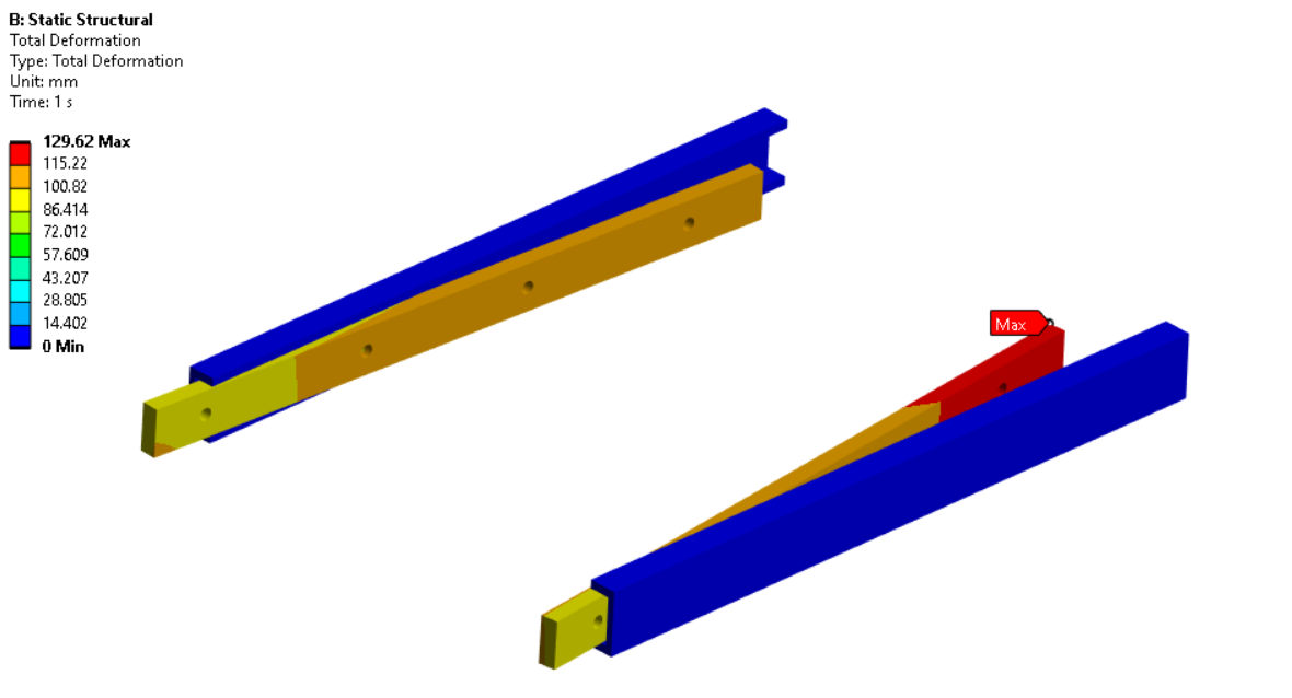
SubscriberHello all, I am working on one sliding mechanism problem where two silde on both sides are carrying a certain weght of 50 Kg which i have attched as point mass as shown in below fig, I contact is firctional with 0.02 coff. i have tried this problem in two approaches in first i have given displacement to two slides 100 mm and second i considered expanded stituation (extrem point withount any displacement) and solved but in both the cases i am getting different results with huge difference. Why?
-
October 14, 2024 at 11:46 am
peteroznewman
SubscriberPlease show what geometry was scoped to in the 100 mm displacement. If you scoped an end face of the slides, that creates a support that is not present in the simulation with the slides positioned at 100 mm without any displacement support, so I would expect to see a significant difference in results. The repositioning method is closer to the correct boundary conditions for this problem.
-
October 14, 2024 at 2:39 pm
BALA
SubscriberHello Sir, thanks for the reply.
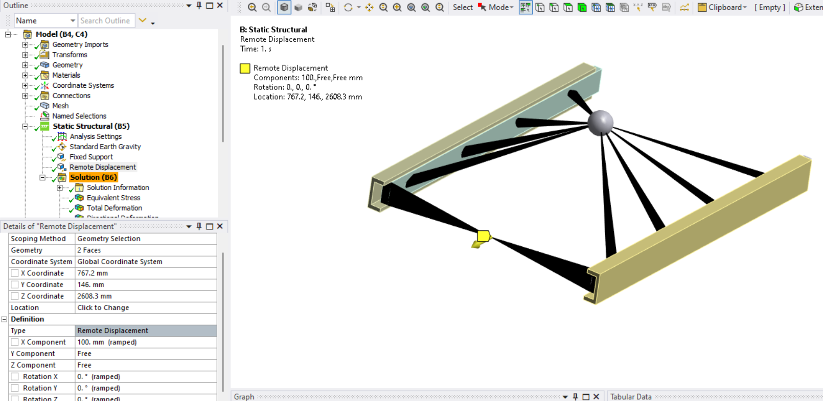
Yess in first approach I have scoped the end faces of two slides for applying 100 mm displacement.In this I have applied X displacement to end surfaces and Y and Z kept zero may be because of that its happening.If it so then what is the way to apply motion and see the end stresses in both the analysis having less difference)
In both the cases point mass is scoped to the 4 holes surfacse which are present on both the slides.
Thanks in advance
-
October 18, 2024 at 1:17 am
peteroznewman
SubscriberDelete the Displacement boundary condition on the two end faces of the slides. That is causing an unrealistic support condition.
Select the two end faces and create a Remote Displacement. Make sure the Behavior is Deformable. Now you can assign an X displacement to the control node between the two end faces, leaving the other five degrees of freedom set to Free. This will move the rails along the slide without any extra constraints except for the X displacement of a single node.
-
October 21, 2024 at 9:21 am
-
October 21, 2024 at 11:09 am
peteroznewman
SubscriberYou need the slides to be attached to a structure such as a drawer. A quick way to do that is to change the remote point supporting the mass to be rigid instead of deformable, but it is more accurate to model the drawer.
-
- You must be logged in to reply to this topic.


-
4683
-
1565
-
1386
-
1242
-
1021

© 2025 Copyright ANSYS, Inc. All rights reserved.

