TAGGED: boundary-conditions, stress-singularity
-
-
October 11, 2024 at 7:17 pm
jvaldes
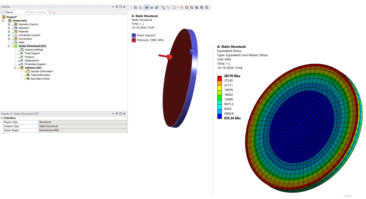
SubscriberI have a part that I am simulating in a Static Structural analysis (see figure 1-3) and I am attempting to validate against a hand calculation (Roark's 7th Ed. Table 11.2 Case 10b: A circular flat plate with a distributed uniform pressure and fixed ends [Compression Only Support C is on the front and the back of the shoulder in figure 1]). They agree (enough) on the stress at the center of the plate. The problem is, the hand calc indicates that the max stress will be at the edge of the boundary conditions; and unfortunately, I have a singularity in the simulation at that location. I then made the simplified model that the hand calc is actually quantifying (see figure 4-5) to try to see if I could come up with some correlation method but I get the same singularity at the edge of the boundary condition (the entirety of both the front and back edge in figure 5) there too. In the actual model, I tried reducing the contact stiffness for the compression only supports, and modifying the geometry (moving the split line out and in, removing it, adding a fillet to the entrant corner there) but all to no avail. I would take the hand calc and move on but I have to produce a report that shows mesh independent convergence at the max stress location. Not sure what to do, anybody got any recommendations?
-
October 14, 2024 at 10:33 am
mohan.urs
Ansys EmployeeHey,
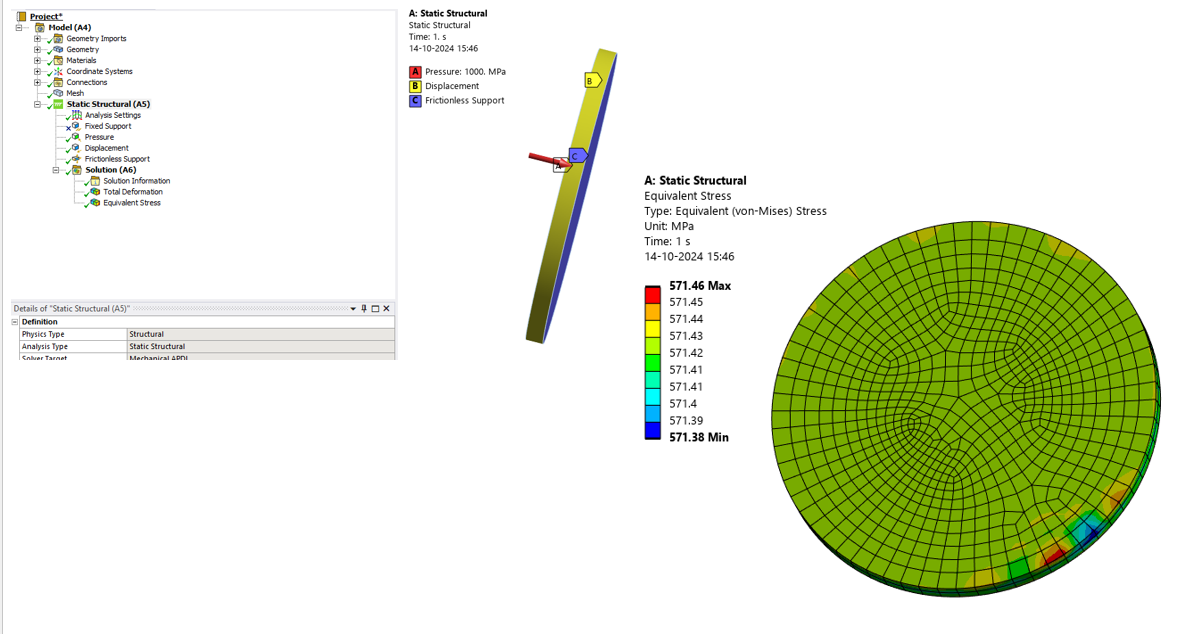
Stress singularity in your 2nd simple case might be due to the over constraint casued by the fixed support.
I have compared two cases below, Do check it out.
First case is similar to yours, whereas in the second. I've used different supports. (displacement to restrain 2 axes motion and frictionless to provide support reaction in one axis). The stress distribution in 2nd is much more realistic.
Stress singularity near boundary condition means that there is a possible support over constraint there.
If you need help on improving the setup, do provide a little more details on your setup.
I couldn't understand the first setup with the images you've shared. Can you please provide a little more insight on to why you chose compression only support and also the max location is also not visible correctly. Do share the location of max stress without the elements.
Thanks
-
October 17, 2024 at 3:53 pm
jvaldes
Subscribermohan,
For the first case, the back side of the component is the same geometry as the front. The main difference is that there is no pressure applied to the back side as it is isolated by the o-ring grooves. (Obviously there are o-ring grooves on the front side as well. This analysis is for a worst-case condition where only one side is pressurized. The o-ring grooves on the front are for a different, less conservative, mounting configuration which would isolate out the front from pressure as well.) The back side is also constrained like the front: "Compression Only Support C" is applied to the back of the shoulder in the same way you see it applied in figure 1 from the original post. I used the compression only as it's a more realistic constraint for this application (see figure 1 here). That being said, I can’t use the full coverage support you show in your second setup, I can only hold a rim rather than the whole back side, basically an annulus with Ø2.8 OD and Ø2.7 ID.
Also here are a series of hopefully clearer pictures outlining the stress. The green “line” of stress there (seen clearest in figures 4 and 5) that makes it’s way around the shoulder is the ID of that annulus and is a singularity all the way around at the edge of the compression only boundary condition.
-
- You must be logged in to reply to this topic.


-
4683
-
1565
-
1386
-
1242
-
1021

© 2025 Copyright ANSYS, Inc. All rights reserved.


