Ansys Assistant will be unavailable on the Learning Forum starting January 30. An upgraded version is coming soon. We apologize for any inconvenience and appreciate your patience. Stay tuned for updates.
General Mechanical

General Mechanical

Topics related to Mechanical Enterprise, Motion, Additive Print and more.

Average and Unaverage stress

    • RoyalFlowers
      Subscriber

      Hi everyone,


      I have a question about average and unaverage stress. As I know if these two values are different, it is a sign that element size is not fine enough. But if by local mesh refinment the maximum average and unaverage stress values still can not match and converge two a same value, could we assume that this maximum area is a singularity due to sudden change in geomtry and report the stress value some nodes away from this singularity?


      I am grateful if someone could advise me in this regard.


      Best regards, Shabnam Samsami

    • Sandeep Medikonda
      Ansys Employee

      I don't think you can use just that understanding to conclude about a singularity.


      As Peter says in one of the posts below:


      A singularity in the model is demonstrated by plotting maximum stress vs element size. If the maximum stress keeps increasing for each reduction in the size of elements around that stress, then that is a singularity.


      Post 1


      Post 2


      Post 3

    • RoyalFlowers
      Subscriber

      Thanks for your answer. 


      Actually, the maximum stress which is really a tiny red spot occured arround a hole, and I used mesh refinment of hole cross section. It is interesting that by incearsing refinment factor the Maximum stress remain constant but still there is a huge difference between averaged and unaveraged maximum stress. due to that I thought that this point is a singularity. Should I focuse on the stress value around the hole and check it with elemnt size inceasment instead of Maximum stress. Last but not least, since this maximum stress ocuured in a really small area arround the plate hole it indicates stress concentration due to sudden change in plate geometry, I think that it is a singular point and I decided to report stress values one node a way from that.


      I am grateful for your furture advice in this reagrd in advance.


      Sincerely, Shabnam


    • peteroznewman
      Subscriber

      It's not just a hole, it is a hole with a bonded contact with a screw.


      It is the bonded contact that is causing the single high stress point.


      With a bit more work, you could refine the mesh on both the hole and the screw and replace the bonded contact with Frictional Contact and use Contact Geometry Correction: Bolt Thread.  That might get rid of the "hot spot" and give a much more realistic stress distribution around the hole with the screw in it.


    • RoyalFlowers
      Subscriber

      Dear Peter,


      Thanks a million for your illuminating answer.


      The point is that our current FE mode is validated by assuming bounded contact between hole and screw. The aim of evaluating von Mises stress is to compare two different FE modes with the same settings and a different geometry of bone fracture. Since the aim is comparing two models with the same FE assumptions, can I report the stress value of the mentioned hot spot of plate or should I ignore this hot spot and report stress values 1-2 node far way from the local hot spot?


      Sincerely, Shabnam

    • peteroznewman
      Subscriber

      Dear Shabnam,


      In the FEA community, the word "validated" means that FE model results were compared with experimental results. Is that what you mean?


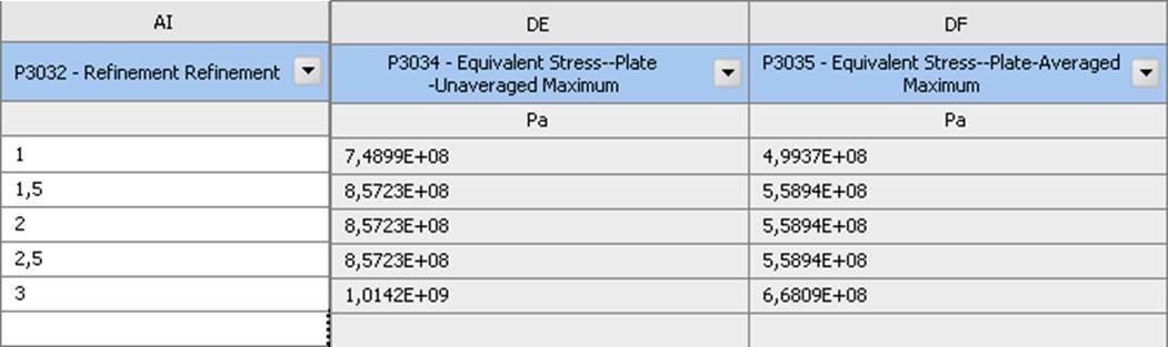
      If you mean comparing one FE model with another, that's not the same as validation because if there is a difference, which one is correct?  When you have a physical measurement on hardware, that is correct and if the FE model predicts a very different value, then the FE model is wrong.


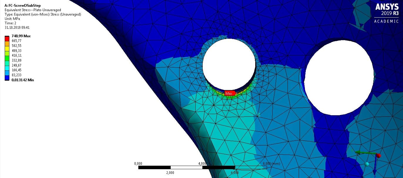
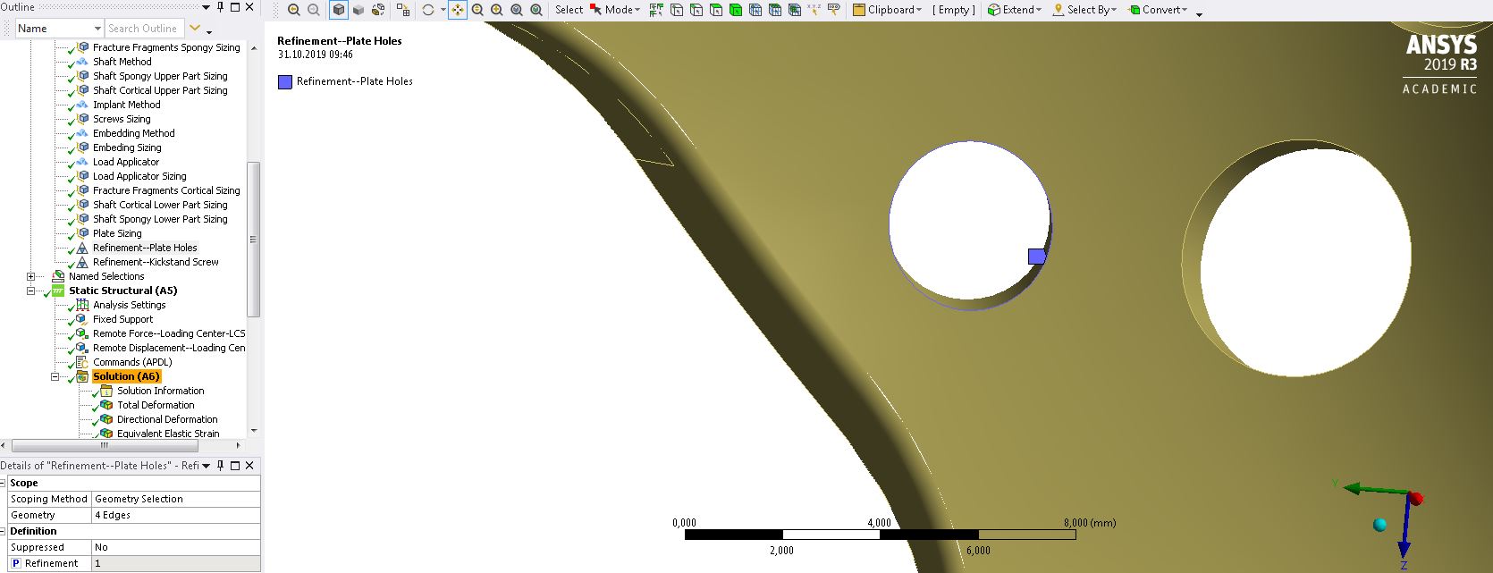
      If you want to compare two FE models with different geometry, then you obviously want them to have the same assumptions. The good assumption is the Bolt Thread Contact Geometry Correction. It will get rid of the hot spots in both models.


      Kind regards,
      Peter

    • RoyalFlowers
      Subscriber

      Hi Peter, 


      Thanks for your answer. Maybe I should clarify the aim of our FEM more. Actually, tow FE models including different fracture geometry were prepared with the same assumptions regarding contacts, material propeties and so on. Then for validation of both models, the global stiffness and some local displacements were compared with experimental data. The obtained numerical outcomes showed an acceptable accuracy. Now I would like to compare these two FE models regarding stress distribution of plate. I mean that sicne models are validated it is difficult to change contact settings because the whole passed steps should be repeated which is really time-consuming. I totally agree with you that Bolth Thread assumption is more realistic and MPC contactt was a simplification, but I would like to know what is the best option to report the stress values in the current model. Is that reasonable to report stress value 1-2 node far from hot spots, and compare them between two mdels? Also, one of limitations of the current FEM could be the simplification f contact between plate and screw which resulted in the local stress concentrations.


      I am grateful if you could advise me in this regard.


      Best regards, Shabnam Samsami

    • peteroznewman
      Subscriber

      Dear Shabnam,


      The validation was done on local displacements on specific areas of the model.  Compare the stress results between the two models in those specific areas. I expect those areas don't include the hot spots.


      Kind regards,
      Peter

    • RoyalFlowers
      Subscriber

      Dear Peter,


      Thanks for your reply.


      According to your explanations, since the local displacements of bone fracture fragments were validated agains experimental data, I cannot report the stress distributions on the plate? Or Could I report the von-Mises stress values of the plate but far rom hot spots?


      My another question is regarding average and unaverage von-Mises stress values. How much difference is acceptable between them? Should we ceck the avergae and unavergae stress values to be sure that out element size is fine enough? or Is normal mesh convergence test sufficient?


      I am grateful for your kind help in this regard in-advance.


      Sincerely, Shabnam

    • RoyalFlowers
      Subscriber

       Dear Peter,


      I am thanksful if you could please answer me my last post as follows:


      According to your explanations, since the local displacements of bone fracture fragments were validated agains experimental data, I cannot report the stress distributions on the plate? Or Could I report the von-Mises stress values of the plate but far rom hot spots?


      My another question is regarding average and unaverage von-Mises stress values. How much difference is acceptable between them? Should we ceck the avergae and unavergae stress values to be sure that out element size is fine enough? or Is normal mesh convergence test sufficient?


      Sincerely, Shabnam

    • saifali
      Subscriber

      Is it possible to share the file

    • RoyalFlowers
      Subscriber

      Unfortunatly the filesize of simulation is a little bit larg to share

    • saifali
      Subscriber

      You can do compression by WinRAR and communicate on the Telegram program

    • peteroznewman
      Subscriber

      Dear Shabnam,


      As mesh refinement occurs, the difference between averaged and unaveraged element results should reduce. I haven't studied what an acceptable error is between them.


      Kind regards,
      Peter

    • peteroznewman
      Subscriber

      Dear Shabnam,


      Another thread provided two opinions on acceptable level of stress element error.


      PDF from 2002


      Blog


      Kind regards,
      Peter


    • Prasanth Renganathan
      Subscriber

      Hi, 

      I'm trying to simulate the stresses from pressing the edge of a square block on the surface of a plastic component. The stress results were about 50% different between the averaged and unaveraged results. I have refined the mesh to try bring this difference down, but the stress numbers only keep increasing and the difference doesn't reduce as the mesh count in the contact region is increased. Does this mean there is stress singularity arising from the sharp edge in contact with the cam? What would be a reliable method to simulate such contact problems? Kindly advise. Thanks!

    • peteroznewman
      Subscriber

      Try adding a nonlinear material model to the plastic material such as Plasticity. That will prevent the stress from increasing too much.

Viewing 16 reply threads
  • The topic ‘Average and Unaverage stress’ is closed to new replies.
[bingo_chatbox]