-
-
September 20, 2024 at 12:52 pm
matt
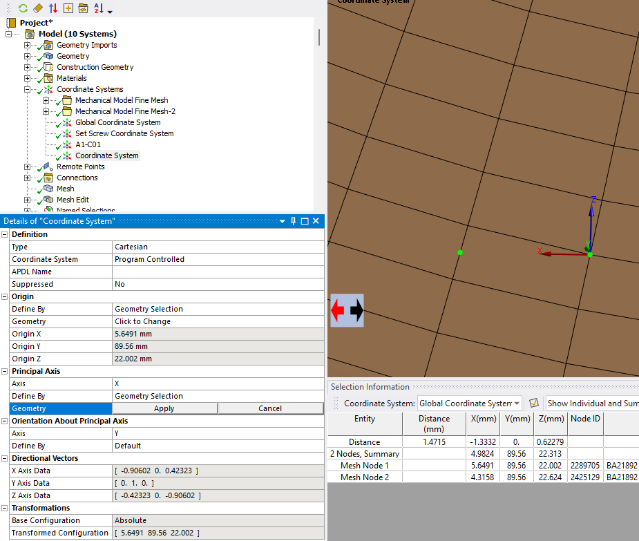
SubscriberFolks, I would like to know if it is possible to create a Cartesian coordinate system in Mechanical whose principal axis aligns between two nodes. In other words, I want to place the origin of the coordinate system at a specific node. I want its X axis to point directly towards another nearby node in the model. I know the CS command in APDL will do it, but I cannot find a way to do this in Mechanical.
-
September 20, 2024 at 1:13 pm
ErKo
Ansys EmployeeHi
What do you want to use that coordinate system for (say apply displacement, etc.)?
All the best
Erik
-
September 20, 2024 at 1:50 pm
matt
SubscriberI need to plot normal and shear strain results along a path. That path needs to have its coordinate system aligned between two neighboring nodes.
-
September 20, 2024 at 2:05 pm
ErKo
Ansys EmployeeHi
There is no automatic way to do what you want, but you can cacluate the direction vector between the nodes and add that to a user defined coordinate system (say being the PrimaryAxisDirection of the coordinate system) in Mechanical.Another way could be to use dierectly in the construction path (Two Points option), to scope Point one (start) to first node and the second end Point of path to the other node.
These are some ideas.
Perhaps forum members have some more ideas.All the best
Erik
-
September 20, 2024 at 3:49 pm
-
September 20, 2024 at 4:33 pm
ErKo
Ansys EmployeeVery good - thanks for sharing.
-
September 20, 2024 at 4:35 pm
ErKo
Ansys EmployeeClosing it since others might find it useful.
(This can be automated also - an example is here: https://discuss.ansys.com/discussion/4432/how-can-we-define-a-coordinate-system-with-x-axis-point-along-a-direction-vector-between-two-nodes)
Thank you
Erik
-
- The topic ‘Coordinate System Aligned to Nodes’ is closed to new replies.


- LPBF Simulation of dissimilar materials in ANSYS mechanical (Thermal Transient)
- Real Life Example of a non-symmetric eigenvalue problem
- How can the results of Pressures and Motions for all elements be obtained?
- BackGround Color
- Contact stiffness too big
- Element Birth and Death
- Python-Script to Export all Children of a Solution Tree
- Which equations and in what form are valid for defining excitations?

-
4592
-
1495
-
1386
-
1209
-
1021

© 2025 Copyright ANSYS, Inc. All rights reserved.


