TAGGED: drag, drag-force, icfd
-
-
September 11, 2024 at 7:26 pm
arnau994
SubscriberHello,
I am running an LS-Dyna model in ICFD, but I have extremely high drag and lift forces, which are 1000 times higher than results from other CFD solvers and published literature. The model set up (boundary conditions, turbulence model, boundary layer set up) are almost the same.
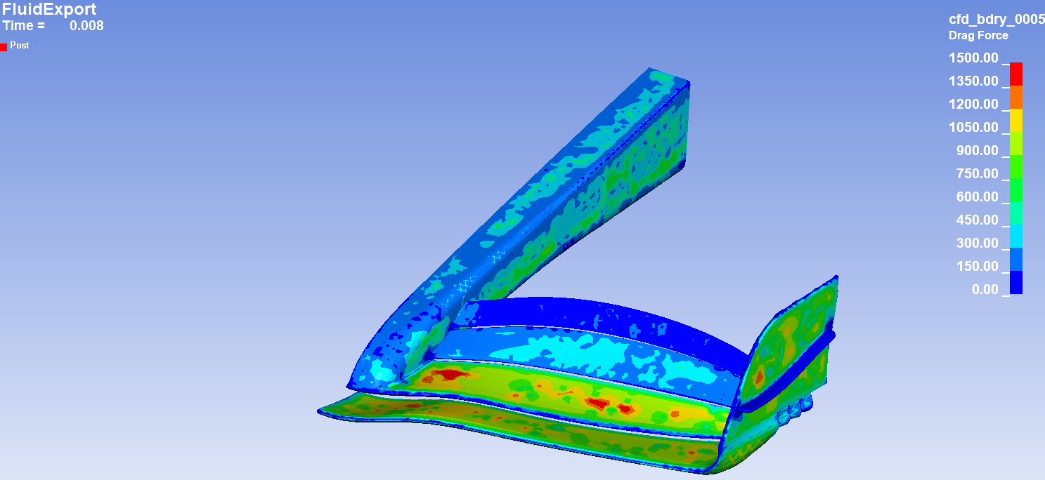
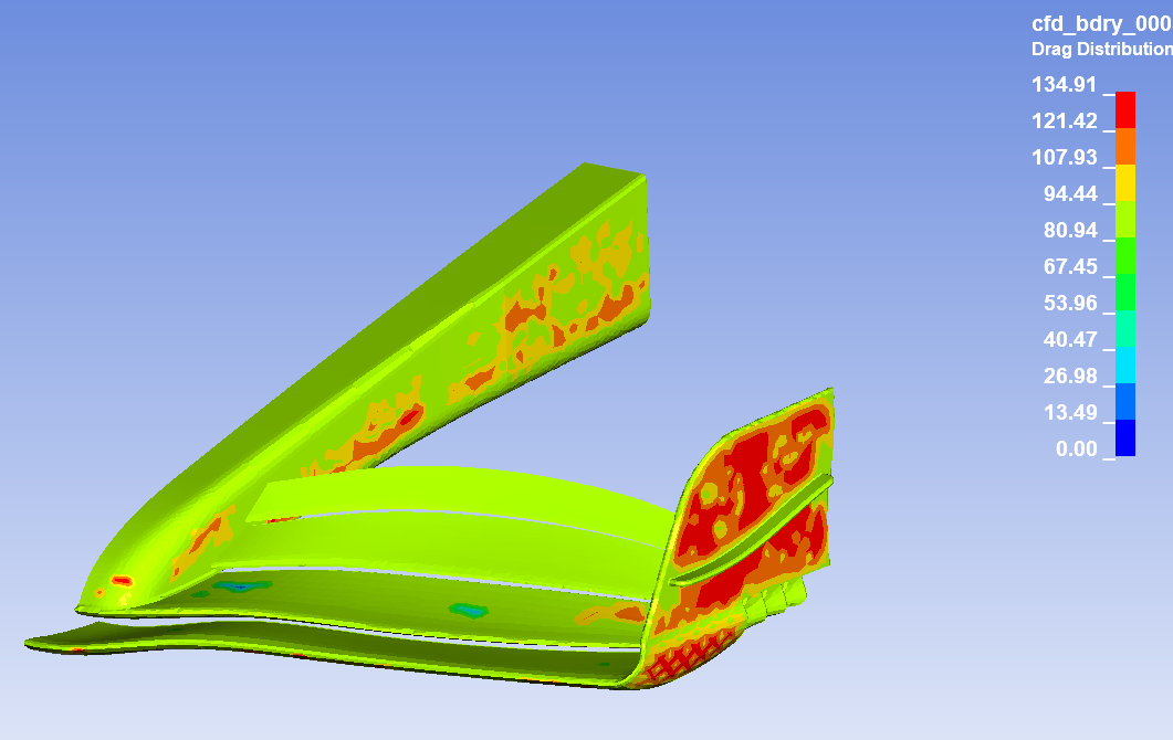
From *ICFD_DATABASE_DRAG, pressure and viscous forces are obtained, and from both .dat generated, I can see that 95% of the force comes from the pressure terms. I have also plotted the drag distribution and the force contribution of each element, and what stands out is that 200N/element are constantly produced independly of velocity, from 2m/s until 50m/s. I have attached the force per element plot in the first image below and the drag distribution in the second image (I still don't completely understand this latter plot).
Does anybody have any clue why these strong forces appear and keep almost constant from low velocities?
Thank you very much,
Arnau -
September 12, 2024 at 4:47 pm
Reno Genest
Ansys EmployeeHello Arnaud,
Which LS-DYNA version are you using?
Are you able to reproduce the problem with the cylinder flow example?
Basics : Cylinder flow — Welcome to LS-DYNA Examples
LSTC QA Test Case Documentation: LSTC-QA-LS-DYNA-ICFD-VAL-3.1-1 (dynaexamples.com)
Do you see different fluid pressure contour plots with different incoming fluid velocities? The pressure drag force is calculated from the pressure as follows:
Have you tried with *ICFD_BOUNDARY_FEESLIP around the body? The ICFD training says the following:
"Warning : in some cases where friction drag is not fundamental, modeling a solid wall
using a free slip condition can give better numeric results than a non slip boundary
condition with a bad quality mesh (incorrectly capturing the boundary layer can lead
to over constrains in the pressure field of the flow)."Give it a try and let me know how it goes.
Note that Ansys employees are not allowed to upload and download files on the Ansys Forum. If you are a commercial customer, please create a support case on ACSS and we will have a look at your specific model:
customer.ansys.com
Reno.
-
September 12, 2024 at 6:59 pm
arnau994
SubscriberHello Reno,
Thank you for your fast response. I am answering your questions below:
1. I am using version mpp d R13, revision R13.1.1-17-ga451ec960f
2. I have run the cylinder example without changing any input data (Re = 100, right?). At 50s, on the icfdragi.dat I get the following forces:
Fpx = -2.622783E-01 Fpy = 9.907471E-02 Fvx = -8.534790E-02 Fvy = 1.326471E-02Which is: Fx = 0.347N (cD = 3.53) and Fy = 0.112N (cL = 1.14). From the icfdraga.dat i get simillar forces on x and considerably lower on y
This does not correlate with page 10 of the pdf that you have attached. Let me know what do you think, as it might be that I am not looking to the correct data.
3. At 10m/s I already have pressures of 2e6 (very homogeneous). At 56m/s, I have pressures that vary between 3.5e6 and 7.5e5. Pressure distribution however makes sense qualitatively. According to published data, pressures should be between 6e3 and 2e4
This makes me think that there is some kind of initial pressure on the model, but the only pressure-related input/boundary condition is at the output surface with *ICFD_BOUNDARY_PRESCRIBED_PRE.
4. I have run the model applying a freeslip condition in the body surface. Now I don’t get any viscosity forces in both icfdraga.dat and icfdragi.dat. Pressure forces are simillar between files, and have decreased by 14% aprox in all x, y and z axes compared with non-slip simulation. But still, they remain in the range of 10^4/10^5, when they should be in the range of 10^2/10^3.
I hope this helps. Thank you very much,
Arnau -
September 16, 2024 at 12:09 pm
arnau994
SubscriberHello Reno,
I am writting this message to let you know that the issue has been solved. The problem was in the density units. On the flap example in the LS-Dyna examples webpage, the units are not in SI. Considering this and that I am not used to the imperial decimal notation (, .) the error went unoticed on my checks.
Sorry for any inconvenience. I hope you have a great day.
Arnau
-
- You must be logged in to reply to this topic.


-
4618
-
1530
-
1386
-
1210
-
1021

© 2025 Copyright ANSYS, Inc. All rights reserved.


