TAGGED: lumerical, Lumerical-FDTD, monitor
-
-
September 6, 2024 at 5:23 pm
pm796
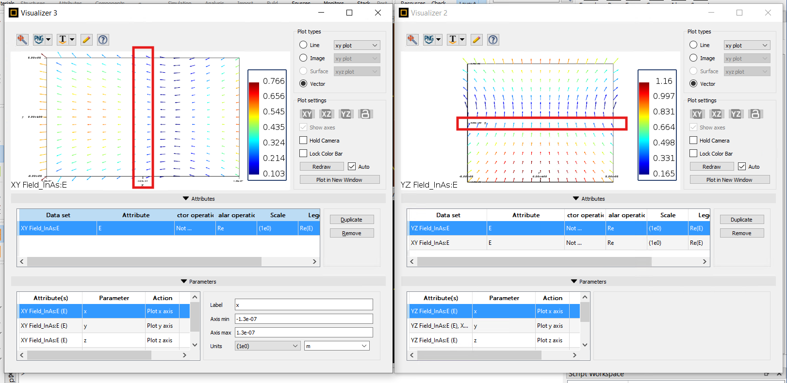
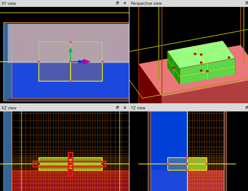
SubscriberI am running a simulation in a cuboid. The XYZ origin is at the centroid of the cuboid. I have two FD monitors, one in the XY plane (plan view) and one one in the YZ (end) plane, both passing through the origin (as highlighted in the red boxes on the green cuboid in the bottom left panel of screenshot 2 below). Looking at the point where the two orthogonal planes intersect (highlighted by red boxes on the screenshots), I am confused as to why at the point where the two slices intersect, the XY results clearly show the E field vectors diverging through the boundaries, but the YZ shows the field vectors at the same point converging. Does anyone know what is happening here, am I missing something?
As an aside, does anyone know if there is any more information on how to interpret results, units, etc in the 'visualiser' panes? The 'reference manual' is quite lacking. Also, the font on the chart in the visualiser is unreadably small - is there any way to change that?
Thanks for your help!
Phil
-
September 9, 2024 at 7:28 am
Ashish Khemka
Forum ModeratorHello,
This seems a duplicate past. I will keep the other one (What is happening with the vector E fields in this simulation? (ansys.com)) open and close this one.
Regards,
Ashish Khemka
-
- The topic ‘What is happening with the vector E fields in this simulation?’ is closed to new replies.


-
4592
-
1494
-
1386
-
1209
-
1021

© 2025 Copyright ANSYS, Inc. All rights reserved.


