TAGGED: joints, spherical-joint, static-structural
-
-
August 27, 2024 at 9:51 pm
Owen Brandriss
SubscriberHello! I'm trying to model spherical/ball joints in an ansys mechanical model and getting strange results. My static structural setup is shown in the image below. I'm applying forces to the bottoms of those 4 shafts, and the blue surfaces of the shafts are modeled as frictionless supports. I want to model a spherical joint to connect each shaft to the star-shaped plate at the location indicated by the green box.

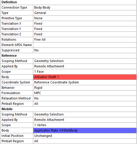
Below is a close-up of this joint. In the orange box is the top surface (the connection point on the bottom of the plate) and in the blue box is the bottom surface (the connection point at the top of the shaft). The idea is to set it up so that the two surfaces are free to rotate relative to eachother in all directions, but the space between the centerpoints of the two surfaces remains constant. I have tried a variety of joint methods, but they all produce the same strange result (also supplied below). My current method is a general joint between the top face of the shaft and a vertex at the center of the connection surface of the plate, with free rotational DOF and fixed translational DOF, as shown in the screenshot below. I tried a spherical joint connection and got very similar results.
My three questions are: 1.) Why are the shafts expanding radially when they have frictionless supports applied to their outer face? 2.) Why doesn't the force appear to be transmitted to the plate through the joint? (when I apply the forces directly to the plate, it deforms noticably) and 3.) How can I model the joint so it behaves like I described above? Thanks in advace!
-
August 28, 2024 at 3:01 pm
mjmiddle
Ansys EmployeeThe shafts expand radially because rotation of the shaft is an unconstrained degree of freedom. They may not rotate at all or they may rotate at a large angular velocity, causing them to expand radially. Be sure to constrain that on each shaft, and maybe the results on the rest of the model will make sense.You could do that with a remote displacement, but it may interfere with the frictionless supports if applied to the same faces. Another way: for the general joints, set reference scoping on the shaft side and fix the rotation direction aligned axial with the shaft.
-
- You must be logged in to reply to this topic.


-
4803
-
1576
-
1386
-
1242
-
1021

© 2026 Copyright ANSYS, Inc. All rights reserved.


