TAGGED: act-forcereaction, welding
-
-
August 27, 2024 at 8:40 am
georg.gruber
SubscriberDear Ansys Community,
I'm extracting force and moment reactions at bonded contacts for a weld seam evaluation by nominal stress concept. So, I only extract reactions via FEM and do the stress calculation analytically by hand. I set up a simple example I can entirely solve analytically, to verify my results. I'm not entirely happy with the moment reactions. I try explaining everything as brief as possible.
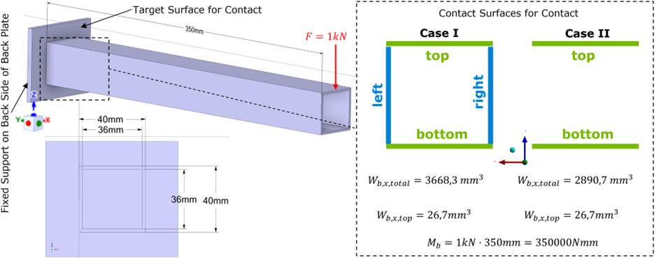
In fig. 1 you see my test case, a simple cantilever beam
Figure 1
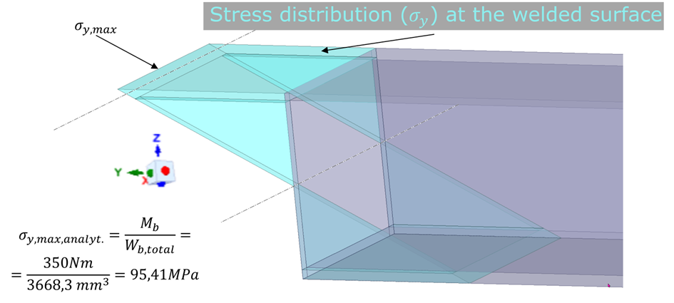
I analyzed two cases I and II. In the following I focus on case I (both cases lead to the same “problem”). The weld seams are assumed to be located directly at the end of the beam (of course that’s not correct, the fillet weld is placed on the outer side of the beam, but let’s keep it simple). The resulting stress distribution is obvious (see fig. 2). I’m calculating sig_y,max analytically and based on reaction forces/moments. The result should be more a less identically. The analytic calculation is shown in fig. 2.
Figure 2
When extracting the reaction moment (RM_x) for the entire contact (therefore I defined ONE SINGLE contact - contact faces: top/bottom/left/right | target face: total face of the back plate) Ansys gives us 350Nm. Same result as derived analytically (see fig. 1 bottom right). All good so far!
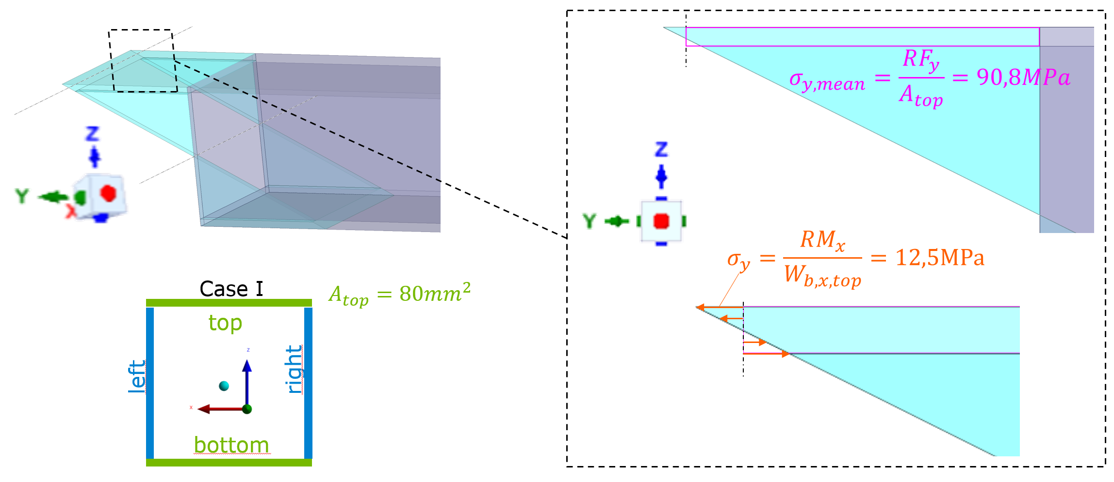
Now I want to calculate sig_y,max (on the upper edge of the top surface, see fig. 3) just by extracting reaction forces/moments of the top surfaces (therefore I split the single contact into 4 contacts, where top, bottom, left, right are glued to the back plate respectively). For the contact “top-surface to backplate” (only this contact will be investigated in the following) I get the reaction force RF_y=7265,4N and reaction moment RM_x=333,4Nmm. Only these are relevant for sig_y acting on the top surface.
Figure 3
The resulting stresses of RF_y and RM_x are calculated in figure 3. For this simple case, the actual sig_y,max can be derived based only on RF_y. RF_y devided by the area of the top surface gives us the mean stress sig_y,mean. Since we have a linear stress distribution and we know the cross section we can easily derive sig_y,max based on sig_y,mean:
sig_y,max = sig_y,mean * (20mm/19mm) = 95,58 MPa
Compare this to the analytical solution sig_y,max,analyt. (95,41) given in fig. 2. This fits quite good (error < 1%). That’s why, the reaction force RF_y is trustworthy to me!
And now we arrive at my problem. Summing up sig_y,mean and sig_y given in fig. 3, should also lead to a correct sig_y,max. However, summing up sig_y,mean (=90,8MPa) and sig_y (=12,5MPa) leads 103,3 MPa. Compared to sig_y,max,analyt., that’s an error of more than 7%. Of course, not super bad, BUT imho too big to be fully OK with it. Does anybody have some helpful ideas? MANY THANKS IN ADVANCE!
Finally, a few more details to the simulation Model:
- Ansys Version: 2024R2
- Mesh: Quadratic tetras with 0,5mm edge length at contact
- Entirely linear simulation
- Material: structural steel, with poison's ratio = 0 (otherwise RM_x for top surface contact event gets bigger)
- Contact:
- Symmetric/asymmetric (not a big difference)
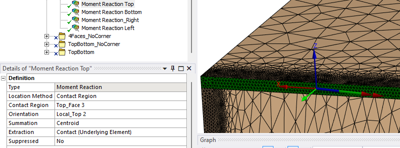
- Moment reaction settings: summation: centroid | Extraction_ Contact (underlying element) --> end of beam is the contact side
- Adjacent contact surfaces can cause trouble (discussed in the forum), that's why I created Case II (see fig. 1), but also here I get too big RM_x for top surface contact
-
August 27, 2024 at 3:36 pm
dlooman
Ansys EmployeeWb,x,top seems to be the section modulus of the top flange. I would calculate that as 40x4^2/6 = 106 mm^2
-
August 28, 2024 at 9:33 am
georg.gruber
SubscriberThanks for the quick reply! Yes you are right, Wb,x,top is the secion modulus of the top flange. The generic equation for a rectangle shape is (width*height^2)/6. However the height of the top flange is only 2mm (see fig. 1, (40-36)/2. –> The top flange AND the bottom flange have a height of 2mm respectively. So in my opinion 26,67mm^3 is the correct section modulus for top flange (and of course also for the bottom flange).
So, still I don't know why I get this unrealisticly high stresses, when summing up sig_y,mean and sig_y :-(
Greetings from Berlin,
Georg -
August 28, 2024 at 1:00 pm
dlooman
Ansys EmployeeSorry, my mistake. Could there be an issue with the moment in the top flange? Is it computed about the centroid of the top flange? I assume you are using fsum and spoint for this.
-
August 29, 2024 at 7:53 am
georg.gruber
SubscriberI also think the issue is the moment of the top flange, since the linear adjustment of sig_y,mean (obtained based on the tensile Reaction Force of the top flange) is very close to the analytic solution.
I'm using workbench. My settings are shown in the figure below. I also had a look at the ds.dat workbench created (located in SYS-ii\MECH). Here I can't find "fsum" or "spoint" when I search (strg+F). I thought all commands used for solving/result extracting should be placed in the ds.dat. Strange, isn't it`?
(Comment: The moment is not perfectly alligned in x-direction. However, I don't think that's my issue. On the bottom flange, the total moment reaction is almost coaxial with the x-axis and the reaction moment around x-Axis of the bottom flange is very close to the top flange result)
-
August 29, 2024 at 2:41 pm
dlooman
Ansys EmployeeYes, unfortunately the postprocessing commands aren't written to the ds.dat file. Only the preprocessing and solution commands. I'm quite sure Mechanical is doing something like spoint/fsum. The centroid is probably computed based on the average node location. You could double check it with a commands object using APDL commands, but I doubt it would differ very much. You're assuming the stress varies linearly through the top flange thickness and the section. Is it possible that assumption is introducing a discrepancy?
-
August 30, 2024 at 8:14 am
georg.gruber
SubscriberFirst of all, thank you dlooman for your perseverance!
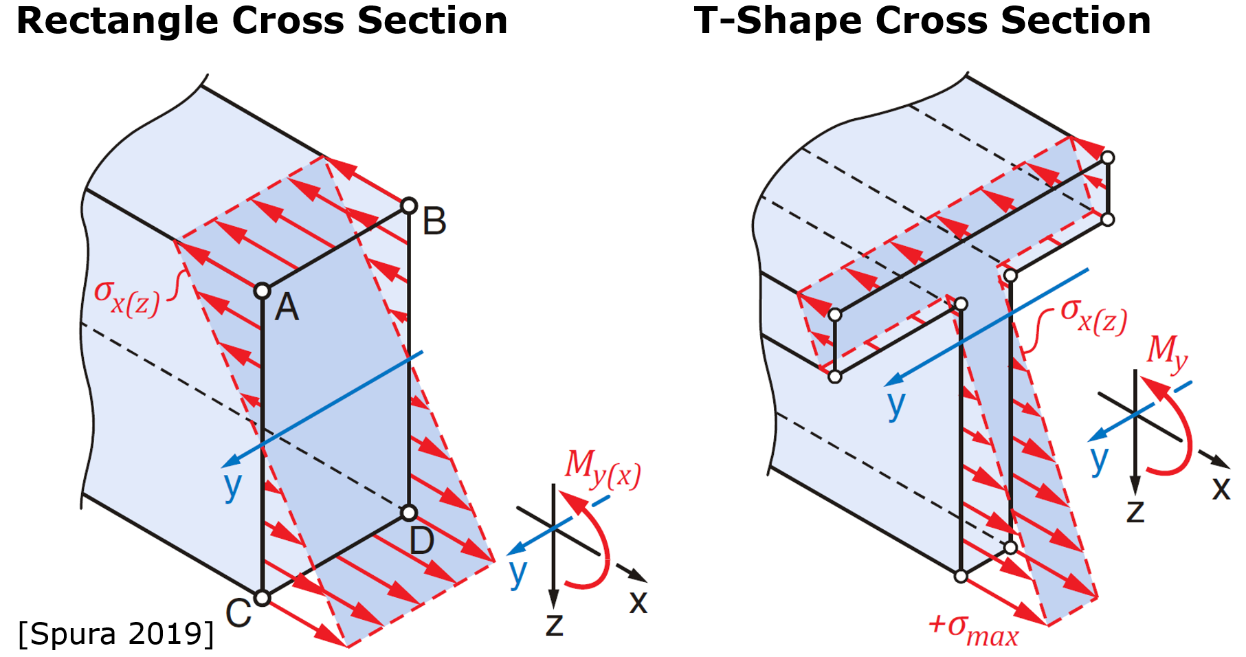
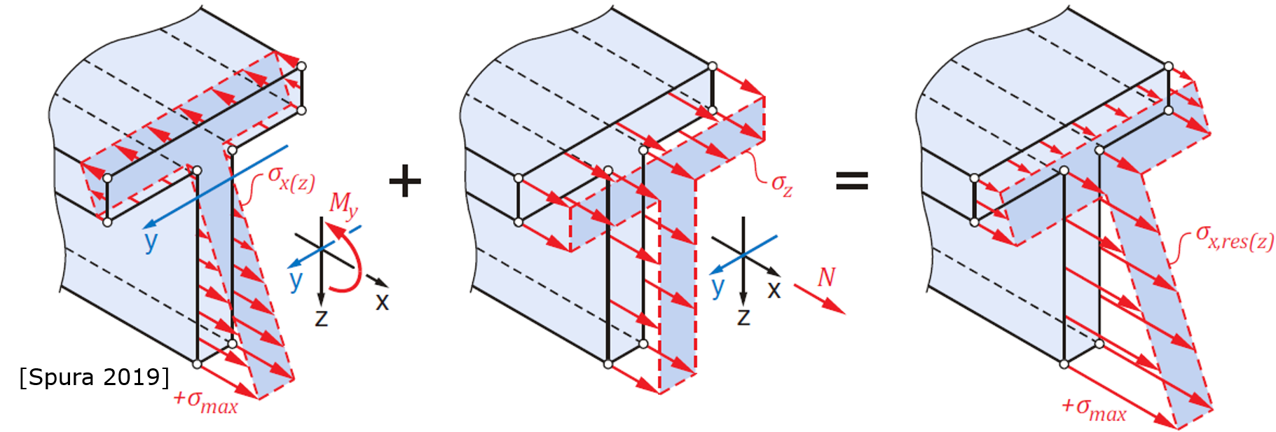
I'm pretty sure there is a linear distribution of normal stress in beam axis direction. I haven't found a nice figure for my example (rectangular pipe), but for standard rectangle und T-shape cross section I found nice figures here Spura 2019 (very nice book by the way).
And even if we neglect the linear distribution. We just can calculate the max normal stress located on the top (or bottom) edge sig_y,max. Continuums mechanics (without any FEM) gives us 94,1 MPa (see fig. 2). And by summing up the constant normal stress and normal stress resulting from bending (see fig. 3), we should get 94.1 MPa. Superposition is definitly allowed, as shown here:
-
August 30, 2024 at 1:40 pm
dlooman
Ansys EmployeeSo it seems either the top flange force or moment is not quite right. The flange nodes share elements with the web nodes. Is it possible the force and moment include a contribution form the webs?
-
September 2, 2024 at 9:15 am
georg.gruber
SubscriberI rather think the moment is the isuue, but you're one of them (Force or Moment) seems to be not correct. The shared edges of top flange and the vertical faces (which are also bonded to the rear plate) are a potential problem. Do you have an idea how to check if that's an isue? So only investigation in that direction is as follows: I also created a case 2 (see fig. 1 right side). Here, the vertical faces are not bonded at all. So in case 2 there are no shared edges of the contact faces. I haven't posted the results for case 2. But it's the same issue. Superposition of bending stress and tensile stress leads to too high stresses sig_y,max at the top edge. That's why I think the shared edge are might not be the problem. But still, it would be worth analyzing this topic.
-
September 4, 2024 at 2:01 pm
dlooman
Ansys EmployeeIf it's worthwhile, APDL could be used as a check on the values in Mechanical. I think it's possible that a small error in the centroid location could create a large error in the moment. The APDL commands would be something like this:
cmsel,s,face ! face is a named selection for the top flange face
esln ! is the tube connected by contact? If so, this command will only select the tube elements and contact elements
spoint,,x,y,z ! x,y,z are the coordinates of the centroid
fsum ! Compare with Mechanical
allsel
-
September 12, 2024 at 1:03 pm
georg.gruber
SubscriberHello, I'm back :-) Thanks for the APDL lines, I had to add one line in the beginning. Here my entire (working) snippet:
SET, last, last      ! Not working without this line
cmsel,s,FACE         ! FACE is a named selection for the top flange face
esln                 ! It doesn't make any difference If I add or uncomment this line
spoint,,-350,330,19  ! x,y,z are the coordinates of the centroid
fsum                 ! Compare with Mechanical
allsel
In the logs I get the result for fsum via APDL, at least exactly the same results as given by the Reaction Moments inside Mechanical. So Mechanical is apparently using the lines above. But, I still don't know where my problem is :-(
-
September 12, 2024 at 1:20 pm
dlooman
Ansys EmployeeWelcome back! :) Perhaps it's just that you're not able to complete isolate the flange elements.
-
- You must be logged in to reply to this topic.


- LPBF Simulation of dissimilar materials in ANSYS mechanical (Thermal Transient)
- Simulate a fan on the end of shaft
- Nonlinear load cases combinations
- Real Life Example of a non-symmetric eigenvalue problem
- How can the results of Pressures and Motions for all elements be obtained?
- Contact stiffness too big
- Test post on Forum – LLM response – SC
- 13-Node Pyramid Element Shape Function
- Element Birth and Death
- Python-Script to Export all Children of a Solution Tree

-
4512
-
1494
-
1386
-
1209
-
1021

© 2025 Copyright ANSYS, Inc. All rights reserved.

