TAGGED: photonics, plasmonics, scattering
-
-
August 22, 2024 at 9:25 am
chenxi.ma
SubscriberDear Ansys staff,
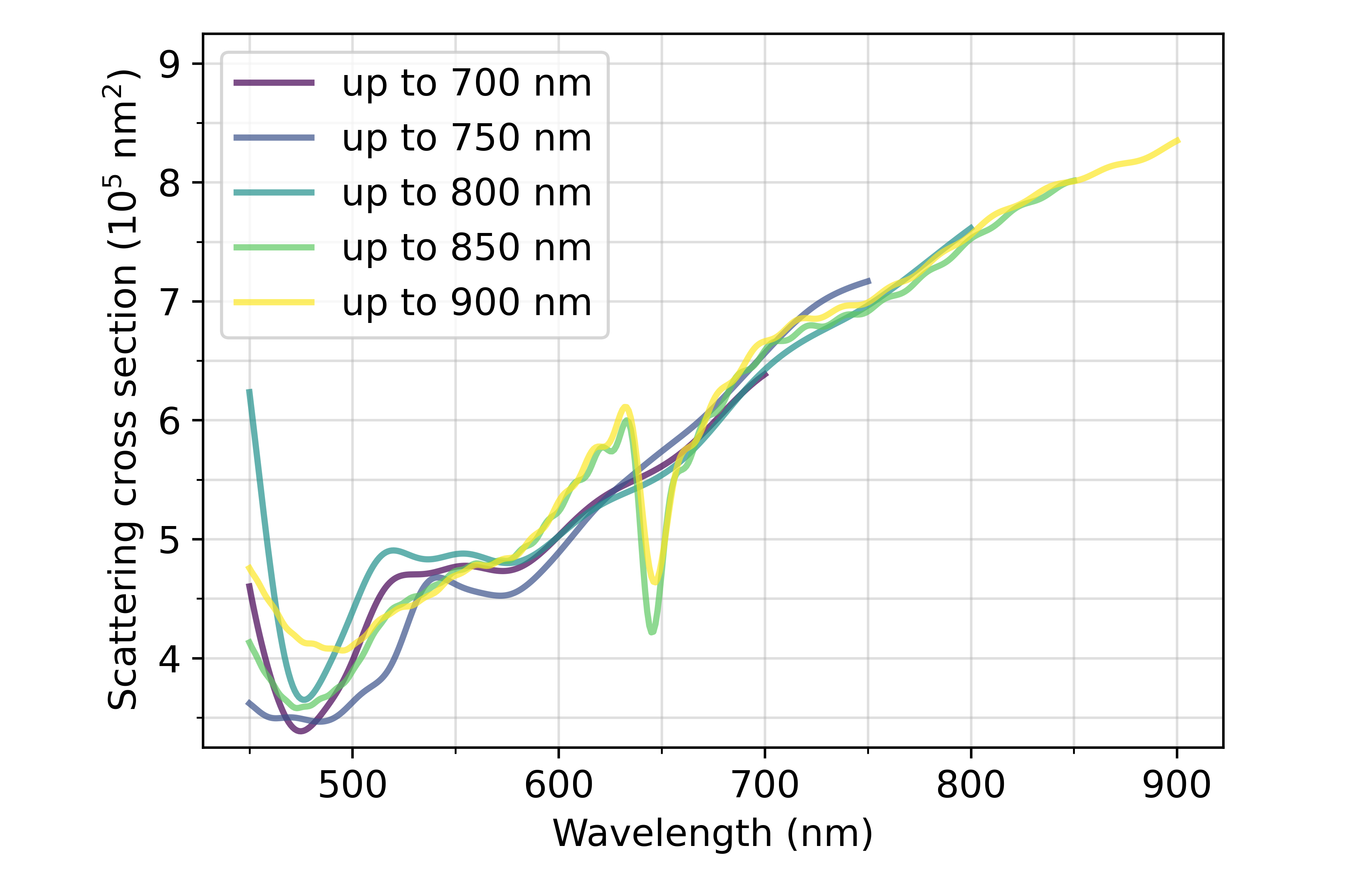
I'm trying to simulate the scattering cross-section of a gold plasmonic structure sitting on silicon. I used the tsfs source and made sure that the plasmonic structure, tsfs source, scat analysis group, and mesh override for the tsfs source are separated at least 2 cells away from each other. I made sure that the simulations were identical, except for the source wavelength range and the corresponding monitor frequency points. However, the results are different for different wavelength ranges.

Could you please kindly help me address the possible reasons?
Thank you very much in advance.
-
August 22, 2024 at 5:29 pm
Guilin Sun
Ansys EmployeeYes, this is normal, since when the wavelength changes, the material fitting changes and thus it affects the refractive index used, and possibly the mesh size (the automesh background).
Please refer to this post:
-
- You must be logged in to reply to this topic.


-
4643
-
1540
-
1386
-
1225
-
1021

© 2025 Copyright ANSYS, Inc. All rights reserved.


