-
-
August 15, 2024 at 4:40 pm
lidianne.pinto
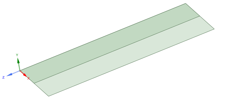
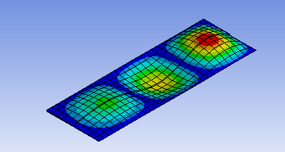
SubscriberI simulated a laminated composite plate that has a 'foot' supported halfway. However, the analytical results are different from the numerical simulation and the numerical simulation presents two different results. The plate has the stacking [-45 90 45 0]s and the 'foot' [45 0 -45 0 -45 0 45]. The thickness of the layers is 0.125 mm. The foot was connected to the plate by bonded contact. The following simulation results were obtained:
The buckling load was 61.958 kN
However, if only a plate is modeled in which half of it has stacking of [-45 90 45 0 0 45 90 -45 45 0 -45 0 -45 0 45] (superposition of plate+stiffener stacking) and the other half of [-45 90 45 0]s, the buckling load obtained was from 181.64 kN
Why did this large difference in buckling loads occur?
When a uniform thickness plate with the stacking of [-45 90 45 0]s is modeled, the buckling load is 62.89 kN . When the stacking of [-45 90 45 0 0 45 90 -45 45 0 -45 0 -45 0 45] is considered, the load is 464 kN.
other question: bonded contact couples all degrees of freedom of the plate and foot nodes with equal coordinates?
If not, how do I do that?
Thank you!
-
August 20, 2024 at 2:01 pm
Govindan Nagappan
Ansys EmployeeCheck the contact definition. Is this a shell model? then, make sure blue and the red faces see each other. You can use the setting "contact shell face" or "target shell face" and switch to top or bottom side.
See if you can use a different contact algorithm. Try MPC instead of the default algorithm.
-
August 26, 2024 at 2:49 pm
lidianne.pinto
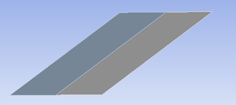
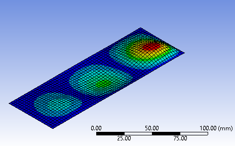
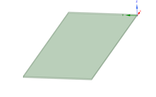
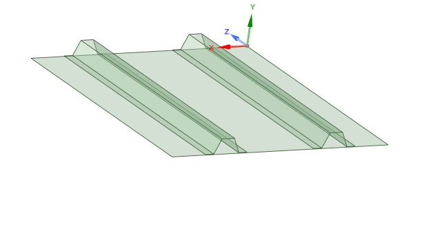
SubscriberDear Govindan,When MPC is considered, the buckling load changes from 61.958 kN to 64.33 kN for the problem described above.When two plates of uniform thickness are stacked (see the figure below), one with a stacking of [-45 90 45 0 0 45 90 -45] and the other with a stacking of [45 0 -45 0 -45 0 45], the load changes from 61.958 kN to 257.46 kN. However, the buckling load of just one plate with a stacking of [-45 90 45 0 0 45 90 -45 45 0 -45 0 -45 0 45] is 464 kN. The analytical solution for this case is 450 kN.What could be happening?I found that when considering a plate stiffened by a trapezoidal geometry without the 'foot', i.e. the flange connecting the stiffener and the skin, the buckling load approaches the load calculated analytically without considering the MPC. However, when considering a stiffener foot, this load diverges even considering MPC. In this case, when not considering MPC the buckling load is 9.5 kN, when considering MPC it is 11.44 kN. Whereas the load obtained analytically is 13.13 kN. The figure below illustrates the case of a plate with stiffener 'foot'.
Thank you,
-
-
- You must be logged in to reply to this topic.


-
4613
-
1515
-
1386
-
1209
-
1021

© 2025 Copyright ANSYS, Inc. All rights reserved.


