-
-
August 13, 2024 at 7:48 am
joel.sayers
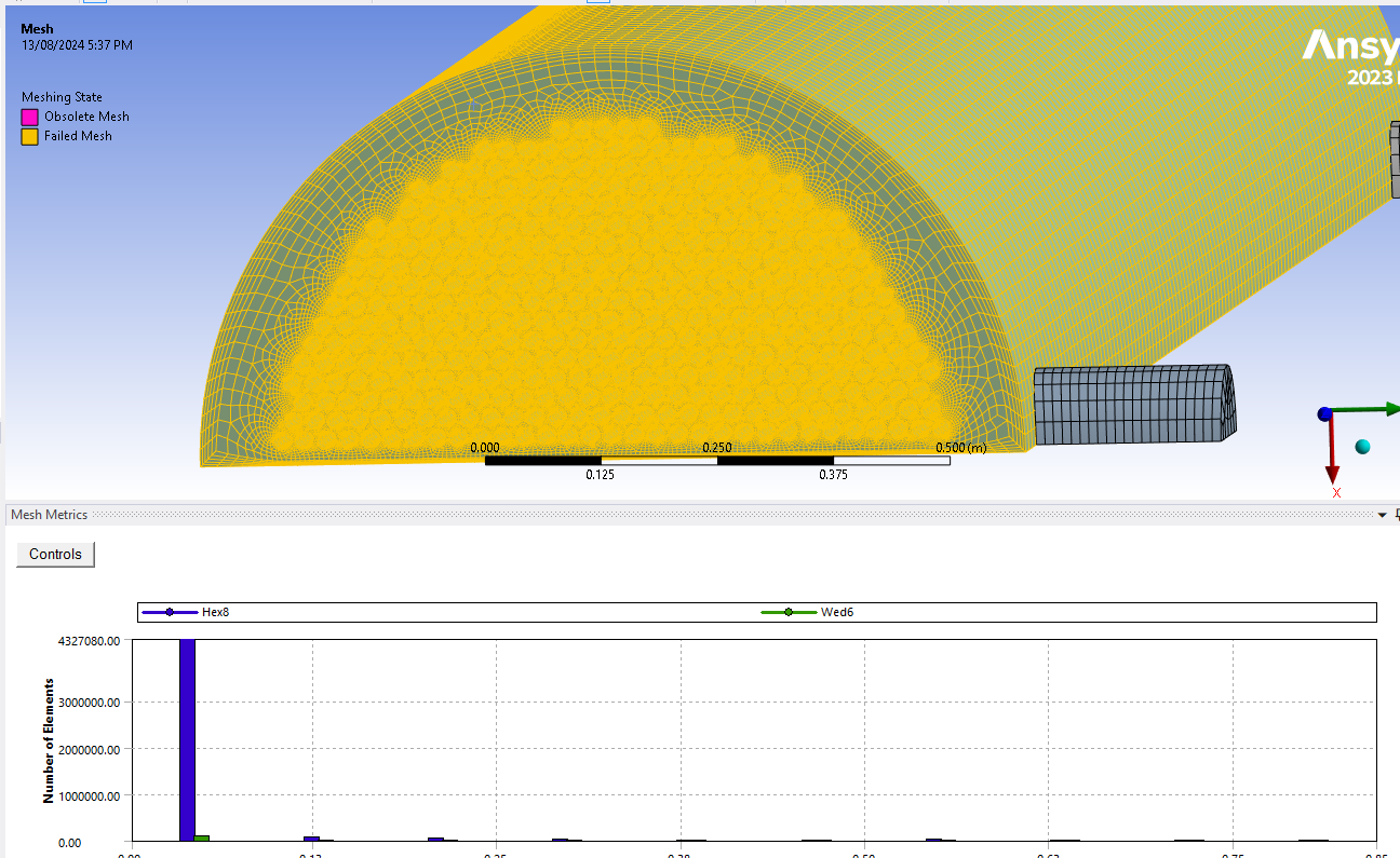
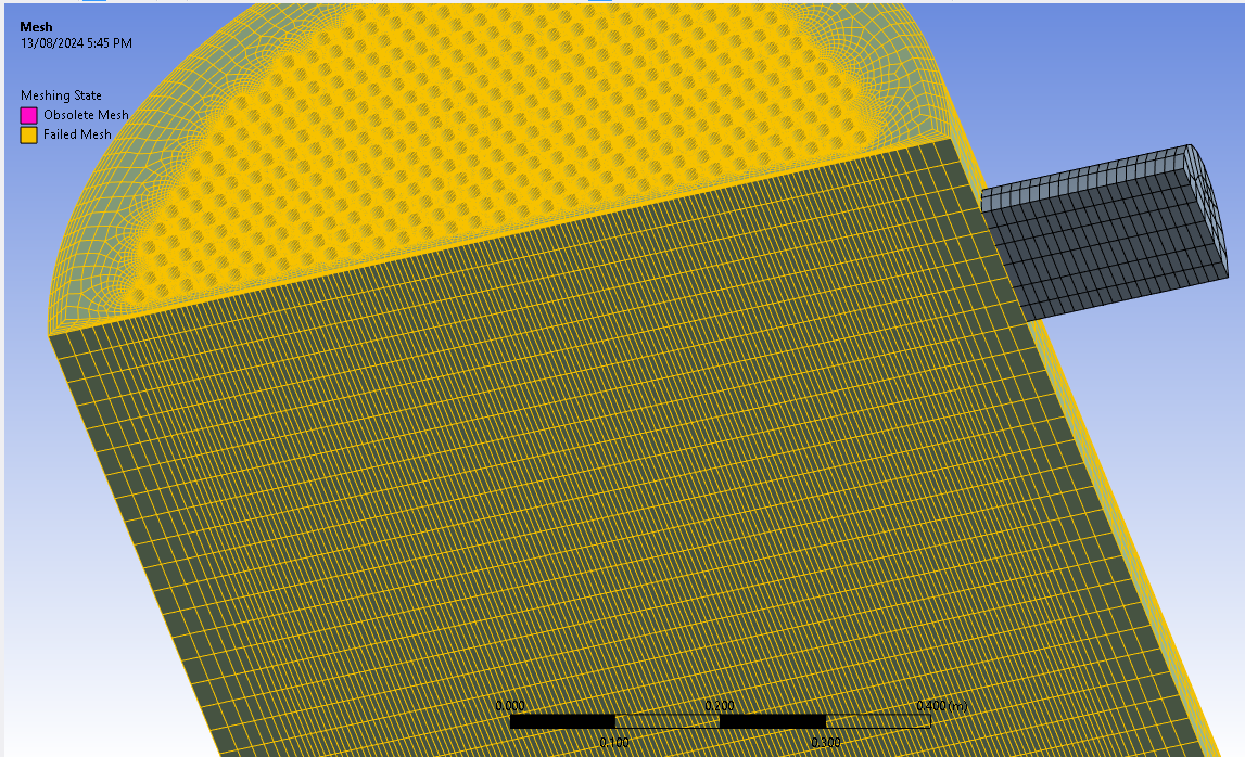
SubscriberHi I've made a post before and it must have been closed but I am trying to mesh half of a shell and tube heat exchanger and only doing the shellside. At the moment I have the domain in sweepable bodies and it meshes fine by sweeping but my element quality is quite poor. I am wondering if there is better ways to mesh or if there is anything I am missing for this element quality to improve.
Thanks
btw -In the pictures the mesh is showing as failed because I have tried something different but stopped it to comr back and take pictures.
-
August 13, 2024 at 10:40 am
Rob
Forum ModeratorAre you using size functions or edge sizing? If the latter are you using hard or soft settings? From there, you're stretching the cells so any cross flow is going to encounter very high aspect ratio cells which isn't good.
-
August 14, 2024 at 10:08 am
joel.sayers
SubscriberYes I have been sizing mainly the front face and using edge sizing for the tube holes, as soon as I try to size the main body it runs for very long and same thing happens when upping the divisions without imporving the mesh quality.
-
August 14, 2024 at 10:19 am
Rob
Forum ModeratorOK, that'll be because of the number of tubes. If you try with the tube sizing and don't set anything for the end face what happens? You may need to alter the cell growth rate.
-
August 15, 2024 at 2:03 am
joel.sayers
SubscriberI did tube face sizing and it runs faster than with the front face sized too, but similar outcome with poor mesh quality.
-
August 15, 2024 at 3:09 am
joel.sayers
SubscriberWhen upping the divisions majorly it slowly is climbing the mesh quality up, this is a nearly 4 metre part as the hot fluid, what do you think is a realistic ball park cell count for this sort of thing as it is now up to nearly 4mil which seems a bit excessive.
-
August 15, 2024 at 9:45 am
Rob
Forum ModeratorDifficult to judge the required cell count as it's a function of domain size and tube count. It is going to be a very high value because of the gap size relative to length. There's a reason we include the porous media model!
-
August 26, 2024 at 7:55 am
joel.sayers
SubscriberOkay thanks Rob, I have had a little look at porous media model. I would just like to ask though could this still apply for a heat exchanger with baffles?
-
August 26, 2024 at 8:51 am
joel.sayers
SubscriberIm having a hard time trying to wrap my head around how to apply it to my problem especially having disc and doughnut baffles. The hot flow itself is would be a porous media due to the tubes or if i used the tubes they would be too, up until the change in geometry with the baffles. Possibly a dumb question, Im guessing I wouldn't be able to scale the model down as an alternative, and it would affect results that can't just be scaled?
-
August 27, 2024 at 9:29 am
Rob
Forum ModeratorYou can combine the porous media with the baffles. So, the fluid has a resistance to flow to account for the tubes but the baffles are actually modelled in the geometry. If you want both sides of the system (shell & tube side) you may need to model the whole lot, or a cut down section if there are any symmetry planes to take advantage of.
-
- You must be logged in to reply to this topic.


-
4602
-
1510
-
1386
-
1209
-
1021

© 2025 Copyright ANSYS, Inc. All rights reserved.


