-
-
August 12, 2024 at 4:53 pm
-
August 13, 2024 at 1:57 pm
K Kramer
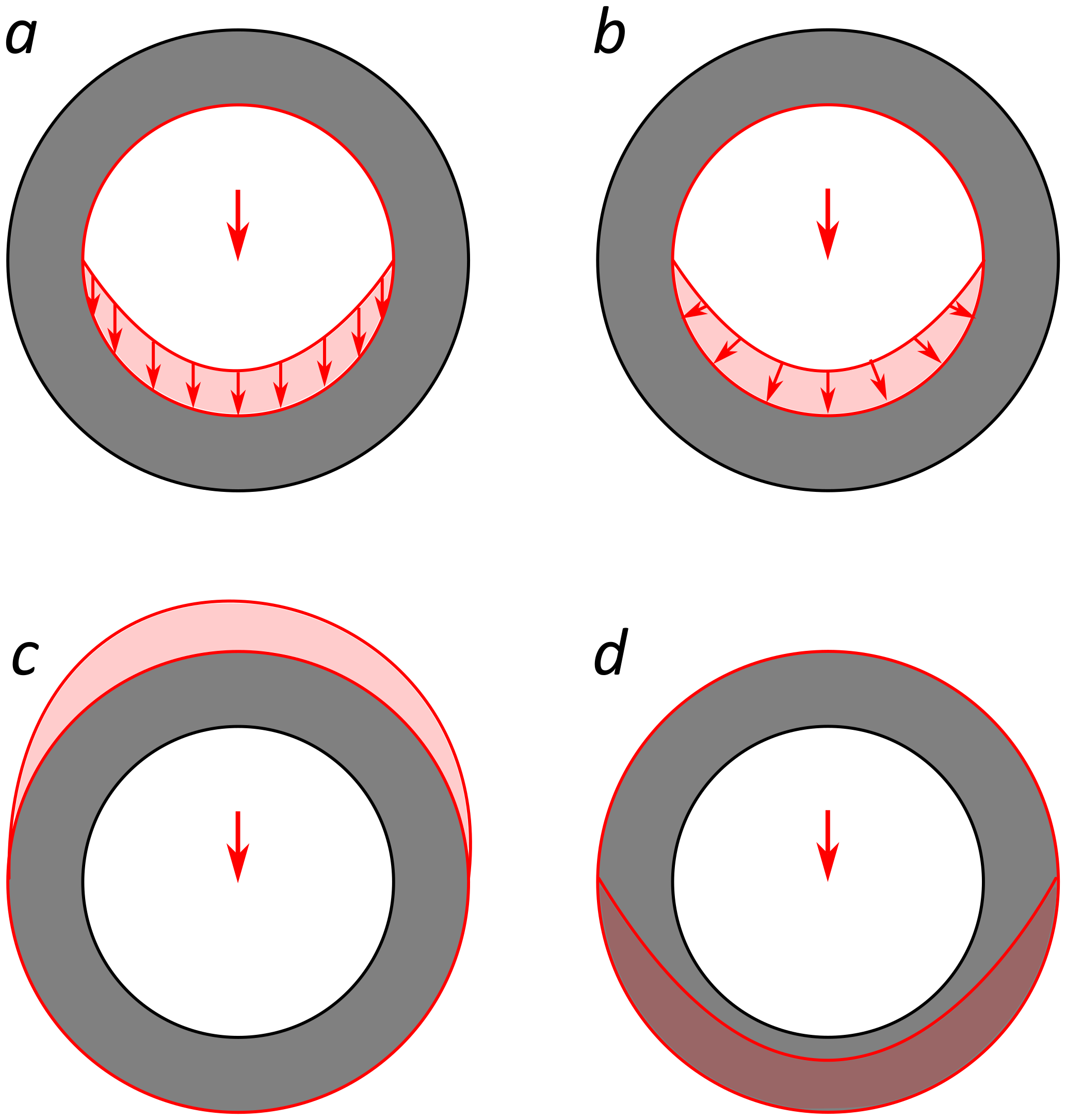
SubscriberAddition regarding the second question: As far as i understand, if a bearing load is applied to a complete rotational inner surface, it will always be applied such that the signs of the distributed load vectors are opposed to those of the surface normal vectors (meaning that the load is always compressive). The question is whether this behavior is maintained when the load is applied to an outer surface (which would correspond to figure c) ) or is "flipped" (meaning the load would become tensile as in figure d) )
In the meantime, I have noticed that bearing loads can also be applied to circular surface segments, which raises two further related questions:
3) Will the angular coordinates of a segment be internally rescaled to a full circle (meaning that if a bearing load is applied to a half circle, it would act on only one quarter of the complete circle)?
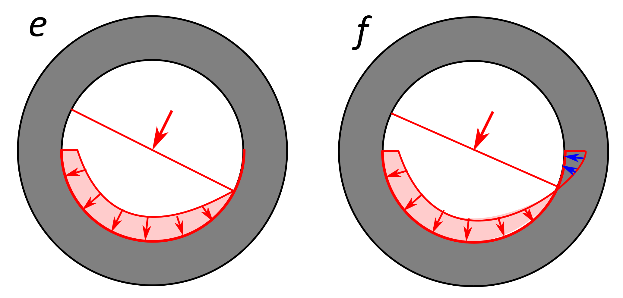
4) For full circular surfaces, there seems to be no possibility to change the load direction from "compressive" to "tensile" or vice versa since a change of sign will simply cause the load to act in the same manner, but on the diametrically opposing side of the surface. What happens if the surface is just a segment of a full circle? Will the parts of the load arc that are acting outside the segment be set to 0 (cf. figure e) ) or will they change direction (cf. figure f) (which would enable a change of the load direction)?
In any case, I would recommend to cover these questions in the documentation and implement an option to change load direction.
-
August 14, 2024 at 12:44 pm
mohan.urs
Ansys EmployeeHey Kramer,
In bearing load the forces are distributed in compression over the area of projection. Here is the link for the additional info 17.6.2.8. Bearing Load (ansys.com)
So in the first case it would be like the figure (a).
For the rest cases i advise you to set up general cases of structural analysis with simple geometry where you put the load on outer surface, cut faces which are inclined and review results like force reaction probes and vector principal stresses to see the effect on them.
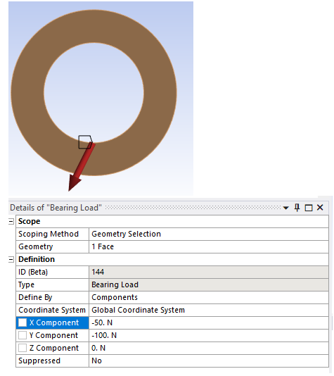
And to answer your other question regarding changing the direction. You should be able to orient your bearing load using the define by - vector (scope edges which depict the direction of load or by components (see attached screenshot below). Do let us know if this is what you meant by direction of bearing load.
Thankyou
-
August 14, 2024 at 3:09 pm
K Kramer
Subscriber-> "You should be able to orient your bearing load using the define by - vector"
Yes, but as I said this will just cause the load to act on the opposing side of the surface, while it is still compressive. It would be good to include an option to change the load direction from compressive to tensile, which is currently not possible.
-
- You must be logged in to reply to this topic.


-
4693
-
1565
-
1386
-
1242
-
1021

© 2025 Copyright ANSYS, Inc. All rights reserved.


