TAGGED: scattered-field, scattering
-
-
July 30, 2024 at 12:20 am
yuqizhu
SubscriberI'm trying to do some scattering cross section calculations following the Mie scattering example. I want to use a gaussian source instead of a TFSF. Does the scattering cross section analysis object work for non-TFSF sources too?
-
July 30, 2024 at 6:29 pm
Guilin Sun
Ansys EmployeeThe methodology is the same. However you will need to do two simulations: w/o the scatter, and their difference is the scattering fields (E &H). then you will need to manually calculate the power from the differential fields. https://innovationspace.ansys.com/forum/forums/topic/ansys-insight-custom-tfsf-source/ unforunately due to forum policy and website upgrades the sampled script screenshots were missing and I could not find the original file. so no script available now.
From my experience as long as the field intensity in front of the scatter is roughly uniform (eg, beam waist is roughly the scatter size), conventional result with TFSF source is about the same as a Gaussian beam.
-
July 31, 2024 at 4:06 am
yuqizhu
Subscriberok, thanks. In my current simulation, the sphere is a lot bigger than the gaussian waist.
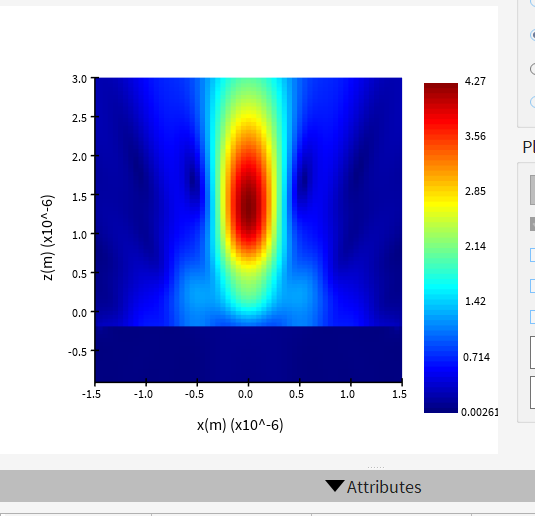
Related to strongly focus beams, attached is a Re(E) map of the beam w/o the scatter (NA=1, using thin lens, linear polarization, proprogate along +z) near the waist and where the scatter would be. why doesn’t this beam profile look gaussian? My source span and simulation span are set to ~50 um.Re calculating scattering cross section from E and H fields, are there examples or internal functions for such calculation? I assume I also need to normalize power and intensity in this process? Also as I understand it, the cross section obj uses transmissions and the soure’s cross section to calculate sigma. So can i just do a differential transmission calculation?
-
-
August 1, 2024 at 8:11 pm
Guilin Sun
Ansys EmployeeJust get the differential fields, calculate the Poynting vector, do the integratio to get the power, and normalize to the source paower. the rest is the same as the conventional TFSF analysis. No internal function can directly get what you want.
Please note it is not differential transmission.
-
August 2, 2024 at 4:52 am
yuqizhu
Subscriberi see. i have a few more questions.
for a gaussian source, is sourceintensity the intensity at the where it is injected?
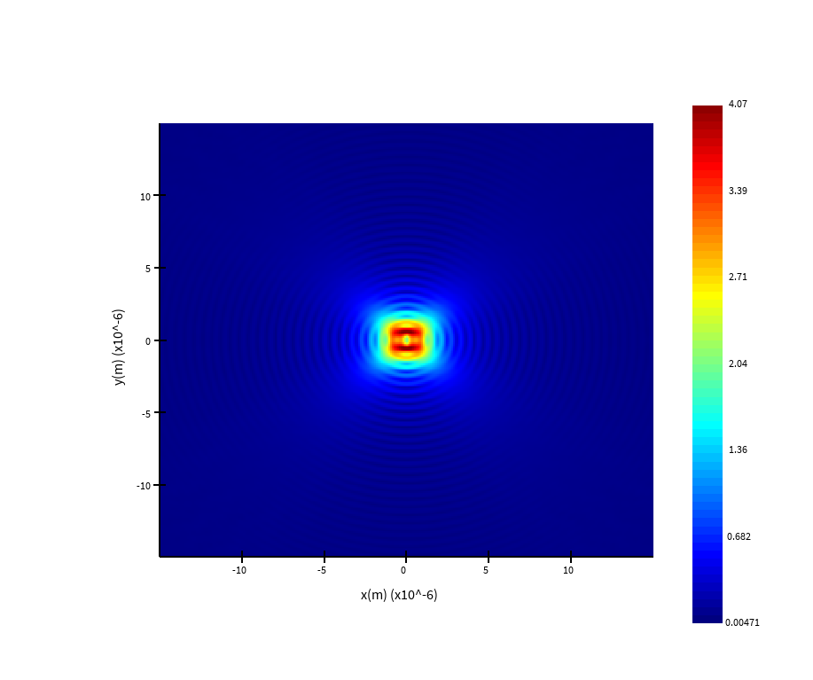
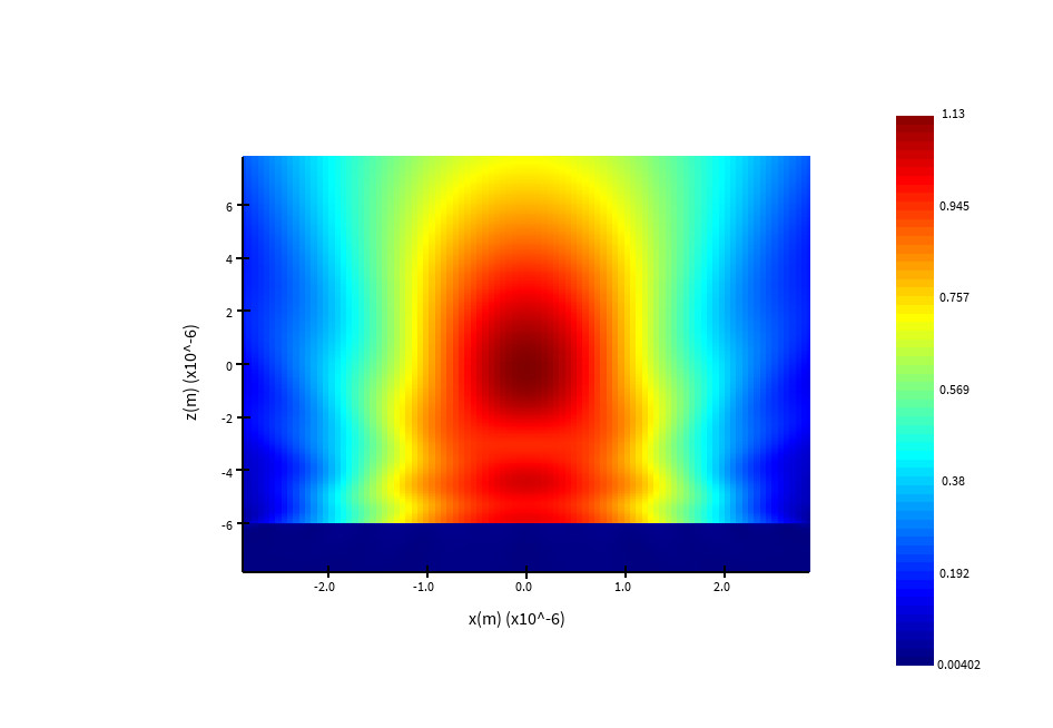
when injecting a gaussian source (use thin lens), there seems to be some artifacts near the plane of injection? attached is a pic of the beam's cross sec; there's nothing else in the model. why are there wrinkles? also, in general, how far should the injection plane be from the scatter? i'm putting it below the scatter.
what is 'power' in the rawdata of a cross sec analysis group? why is it a complex number?
I'm still having trouble setting up high-NA gaussian beams. for NA~1, my E field's z- cross sec's still don't look gaussian with some holes at the center. how do i fix this?
-
August 2, 2024 at 6:51 pm
Guilin Sun
Ansys EmployeeScattering parameters use plane wave by definition. So when you use non-plane wave, you have to decide what quantity to use for the intensity, since abs(E)^2 is space-dependent. You may use the peak intensity, or an averaged intensity, it is up to you.
wrinkles? it might be due to reflection from PML, or source size is small. Here is what I got:

-
August 5, 2024 at 4:49 pm
yuqizhu
Subscriberre high NA gaussian beams, the side normal profile looks ok now after I moved the PML farther out like you suggested. However, the z- noraml cross sections still don't look as gaussian as i'd expect. Here is a screenshot (NA=0.9) in my google drive; I can't upload images today for some reason.
For low NA beams, I have a different problem, (NA=0.11). Both z- and y-normal profiles look wavey. The lower PML in z is ~2.5 lambda way from the injection plane, and simulation span is X/Y is ~15 um. Is this also from some numerical artifacts?
-
August 12, 2024 at 5:30 pm
Guilin Sun
Ansys EmployeeNA beam is diffraction-limited vectorial fields. High NA beam profile will have obvious diffraction pattern, which is correct: https://optics.ansys.com/hc/en-us/articles/360034382854-Plane-wave-and-beam-source-Simulation-object
For low NA, the bem size is large, and al may need better PML performance. Please use larger simulation spans and more PML layers and make sure source is wide enough not cliping the field. You can use log scale to check the intensity at the edge.
-
August 12, 2024 at 6:14 pm
yuqizhu
Subscriberok, thanks.
Following up on the intensity question, I’m getting the power, intensity and area of my gaussian source using the method posted here https://optics.ansys.com/hc/en-us/articles/360034925313-sourcepower-Script-command.
However, i got power =4*intensity*area. This factor appears to be a constant of my other numerical parameters including the monitor size and source size. I’m using anti-sym and sym boundary conditions. But my understanding is that those are accounted for in the sourcepower and sourceintensity functions. Is this factor expected? if not, how do i fix it?
-
August 14, 2024 at 7:39 pm
yuqizhu
SubscriberI have another related question about calculating forces from the same scattering simulation. I looked at the 'optical force on a particle (3D)' example as well as this page https://optics.ansys.com/hc/en-us/articles/360042214594-Methodology-for-optical-force-calculations. As I understand it, the example implemented the methods on the page linked. I thought that, in general, the total force includes a surface integral over the Maxwell stress tensor (3x3 for only the spatial components) and also a time derivative of the poynting vector https://en.wikipedia.org/wiki/Maxwell_stress_tensor. So I wonder if I should also add the dS/dt term for my generic force calculation. When the source is injected into the simulation, and then results in the scattered field, doesn't this contribute to a net dS/dt? thanks.
-
August 14, 2024 at 8:58 pm
Guilin Sun
Ansys EmployeeAnsys optics provides two methods for optical force calculation. There are other methods. You can always develop your own method since it is post processing.
Please write a new post for any questions not directly related to the post.
-
- The topic ‘scattering calculation with gaussian beam in FDTD’ is closed to new replies.


-
4843
-
1587
-
1386
-
1242
-
1021

© 2026 Copyright ANSYS, Inc. All rights reserved.


