-
-
July 12, 2024 at 12:34 am
hossein.hashemidehaghi
SubscriberHi everyone,For the past couple of months, I’ve been trying to validate a discharging cantilever pipe experiment subjected to vertical gravity using ANSYS 2022R1 system coupling in the Workbench. Here are the properties:- internal fluid: water
- pipe length: 94 mm
- inner radius: 1.36 mm
- outer radius: 1.66 mm
- E = 5.4 MPa
- pipe density = 5554 kg/m3
- Poisson's ratio: 0.33
- total run time: 0.5 sec
The image below shows the experimental deflection of the pipe from this article.
I want to derive the transverse deformation of the pipe due to the internal flow with a velocity of 2 m/s. However, I've faced multiple types of error during my attempts. It is worth noting that the simulations worked with stiffer materials like aluminum alloy or structural steel.
At first, I tried with Fluent-Mechanical:
- I followed the Workbench FSI tutorial.
- Encountered negative volume mesh errors around t = 3.3 ms
- Tried multiple timesteps ranging from 0.0001 to 1 microsecond, but the simulation didn’t improve.
- Changed the dynamic meshing method from diffusion to linear elastic and set the outlet as unspecified, but no change.
And currently changed to CFX-Mechanical, but the situation were worse:
- The solution doesn’t progress after 3 to 4 iterations.
- common errors: “MAPDL solution terminated due to DOF LIMIT EXCEEDED” or mechanical force convergence value does not converge, causing unending iterations.
- large deflection was always ON
My overall guess is that the time-step is not the issue. I also, read from the manual that larger mesh cells absorb most of the deformations while smaller ones experience rigid body motion, but I want to avoid adding a surrounding air volume as it introduces complexities due to two-phase interactions.
I'd appreciate a lot if anybody has any idea how to solve this issue. The case itself is very simple and easy to try.
Some other details and images:
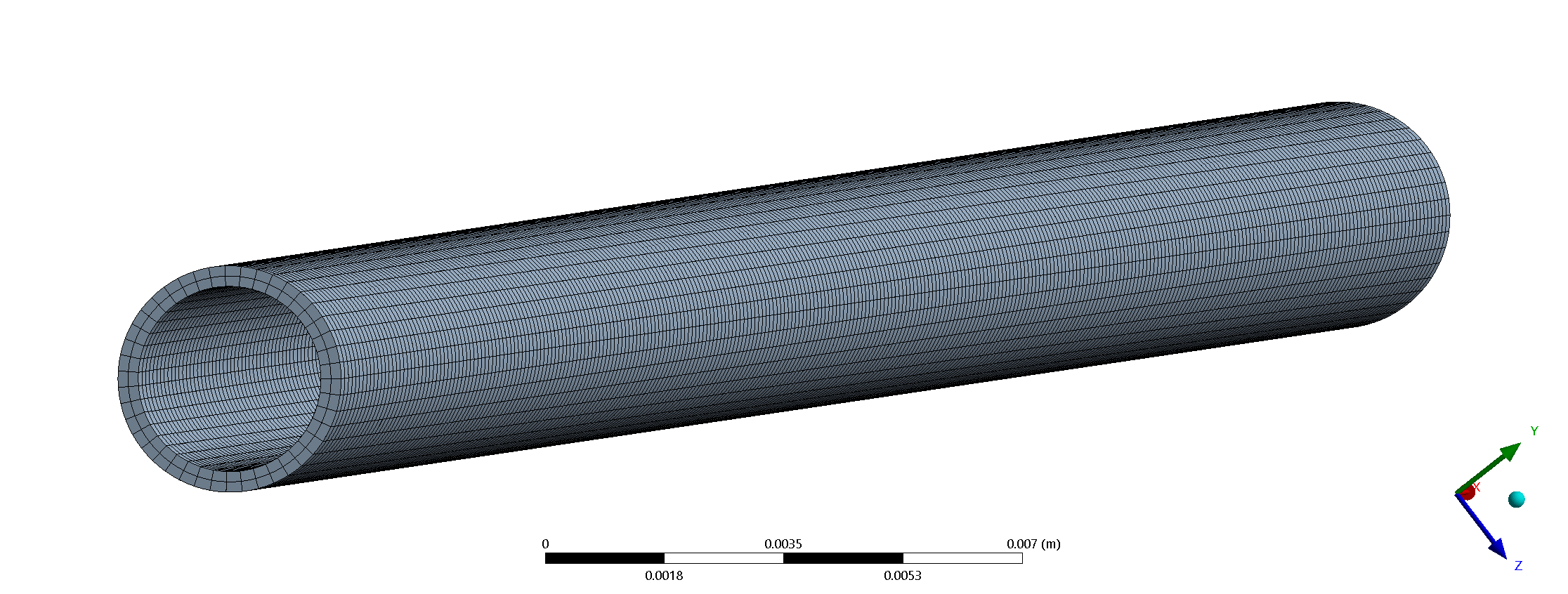
- Pipe Mesh: Aspect ratio about 2, minimum element quality = 0.77.
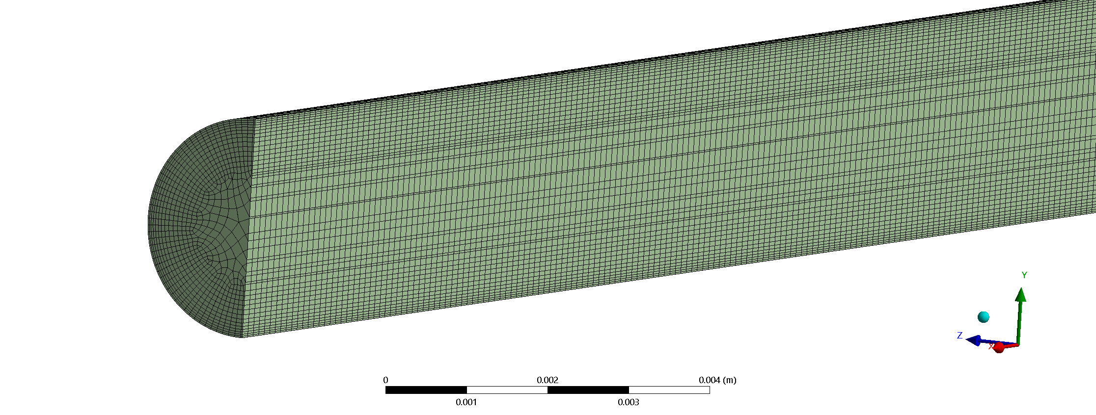
- Fluid Mesh: Maximum aspect ratio is 8.75 (most around 2.5 to 3.5), minimum element quality = 0.28.
- I added a fluid volume upstream of the pipe to make sure the flow inside the pipe is fully developed from the start.
The whole geometry:
Solid mesh:
Fluid mesh:
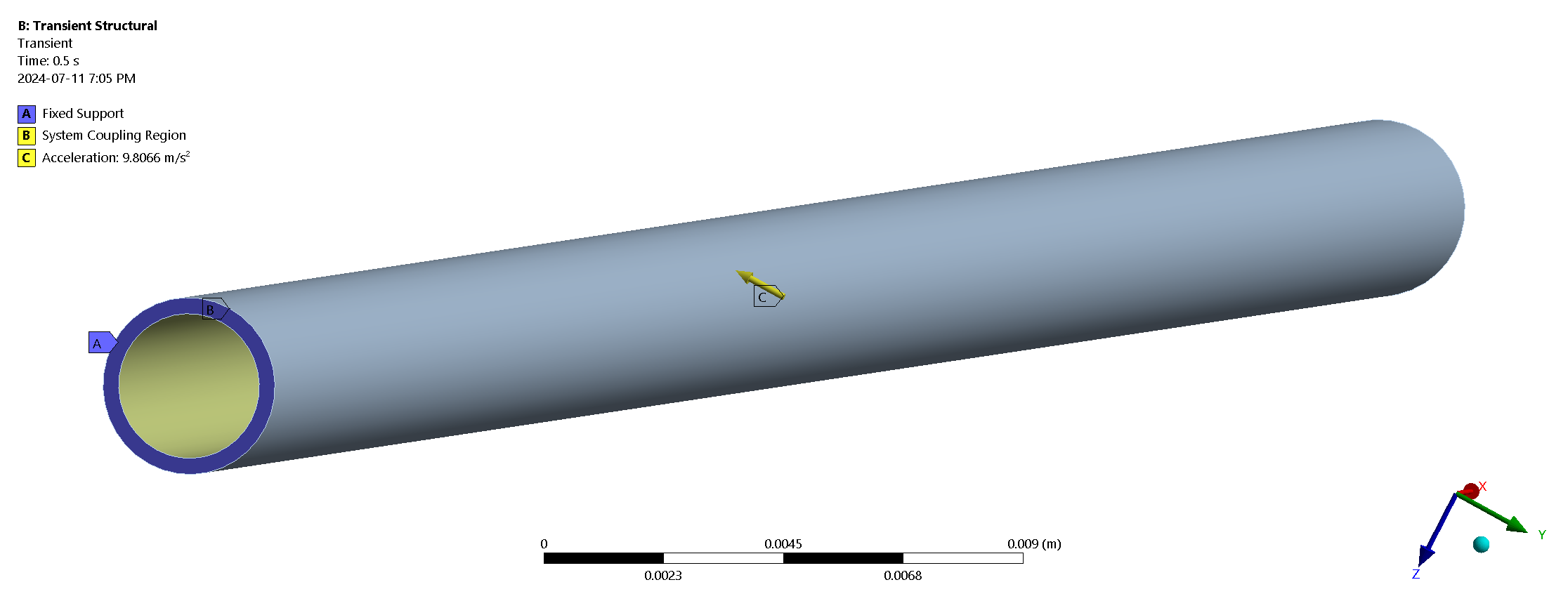
The mechanical setup:
-
July 12, 2024 at 2:42 am
Emmanuel-akor
SubscriberHi Hossein, I had similar challenges with my FSI simuation for airflow in a tube as well but finally got it to work. Negative cell volume is as a result of over distortion or deformation of the pipe. And yes you’re right, decreasing the time step doesn’t help – it didn’t help my case. There were two things I noted that caused this, the “material property” assigned and “convergence”. Aluminum and Steel works because it is pre-defined by Ansys. Nonetheless, your material property seems fine. Are you sure your solution is converging for the “fluid”, “solid”, and “coupled” iterations? If your solution isn’t converging, it means for the iterations that you have, the solutions are inaccurate and might lead to the errors you are having. Remember that the first few iterations are guesses, and the computation might need a few more to arrive at the correct solution. Since I’ve got this to work on my end, I am willing to discuss this in detail via email or look through your file. Also, what does the deformation for Aluminum and Steel look like? Best
-
July 12, 2024 at 9:14 pm
hossein.hashemidehaghi
SubscriberHello Emmanuel,
Thank you for your support. The solutions for steel and Alminium alloy are fine. They have no problem. However, my main intetion is to simulate for a soft material.
This is my email:
hossein.hashemidehaghi@mail.concordia.ca
Send me an email and I will send you my files.
Thanks
-
-
July 12, 2024 at 11:52 am
Rahul Mule
Ansys EmployeeBefore starting an FSI simulation, you should run separate fluids and structural simulations using representative loads.
- Check that the basic setup is correct for each side
- Use settings that are as close as possible to the planned FSI simulation (same time step size, etc)
- If it’s difficult to provide representative fluid loads, you could run a System Coupling simulation with loads passed 1-way from Fluent to Mechanical
There are a number of convergence controls, so it’s easy to head down the wrong path. In general start with:
‒ Default # of Coupling Iterations: Min: 1, Max 5 (for transients)
‒ Default Data Transfer Under Relaxation Factor: 1
‒ Perhaps 5 Fluent iterations per Coupling Iteration (for transients), but this is case dependent.
‒ A Time Step Size based on the physics you need to resolve
• 1/20th of the oscillation period corresponding to the highest structural frequency of interest
• Flow field Courant number.-
July 12, 2024 at 9:29 pm
hossein.hashemidehaghi
SubscriberHi Rahul,
I ran a system coupling 1-way from Fluent to Mechanical, everything seems to be fine until now. But, for the CFX-Mechanical, the System coupling cannot get past the second iteration. The error is always about excessive distortion in Mechanical. I added a slow ramp increase to my inlet velocity and another ramp to my gravity but didn’t work.
-
July 14, 2024 at 7:40 am
Rahul Mule
Ansys EmployeeHello Hossein,
When modeling soft materials in Ansys and encountering highly distorted elements, there are several strategies you can employ. Please refer Handling Element Distortion Errors in Hyperelastic Material Models Using Ansys Mechanical — Lesson 3 (youtube.com) to handle highly distorted elements in Mechanical.
-
July 14, 2024 at 7:09 pm
hossein.hashemidehaghi
SubscriberThank you, Rahul. However, what should be done when the issue is a negative volume mesh in Fluent? Is there a solution besides decreasing the time step? Could the absence of very large cells impact the deformation of the elements? I ran a 1-way Fluent to mechanical. it was fine. then, I ran another from Mechanical to Fluent, where I got negative volume meshe error after about 200 coupling steps.
-
-
July 15, 2024 at 12:28 pm
Rahul Mule
Ansys EmployeeEnsure that you have good quality mesh in Fluent and consider changing the dynamic mesh properties. You can refer 42.6. FSI Setup Recommendations for Fluent-Mechanical Couplings (ansys.com).
-
July 22, 2024 at 7:56 pm
hossein.hashemidehaghi
SubscriberI am currently using the System Coupling GUI with quasi-Newton stabilization enabled. The simulation is progressing well, and I'll provide updates soon. However, I've noticed that System Coupling is only utilizing 10% of the available CPUs. Does anyone know how to set the number of processors in the GUI version?
-
July 23, 2024 at 7:37 am
Rahul Mule
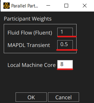
Ansys EmployeeYou can specify, the number of cores to be used for each participant as a fraction of the total cores in the system coupling GUI.
RMB Coupling participant > Parallel solve setup...
Provide total cores to be used. Here in this example fluent will use 8 and mechanical will use 4 cores.

Please refer user guide for more details: Using Parallel Processing Capabilities (ansys.com)
-
- The topic ‘Two-way FSI: It’s impossible to simulate a cantilever discharging pipe in Ansys’ is closed to new replies.


-
4833
-
1587
-
1386
-
1242
-
1021

© 2026 Copyright ANSYS, Inc. All rights reserved.


