-
-
June 4, 2024 at 10:20 am
rohitshivalli22
SubscriberHI,
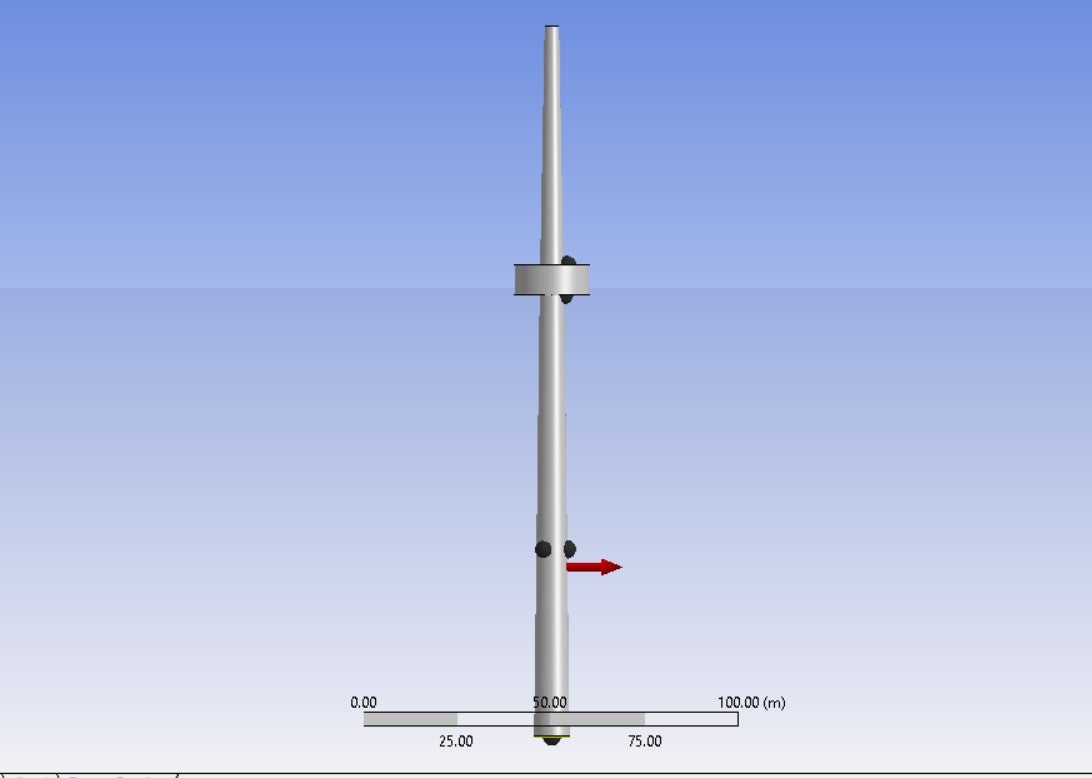
I am trying to analyze a model in hydrodynamic diffraction, i have created two structures in space claim with gap 0.75m between them and i need to connect them using fender connection for relative motion in vertical direction i.e., in z direction, and i don't know what is the procedure to perform it. if anyone knows about it please guide me to attain the final result. a picture of the model has been attached
-
July 8, 2024 at 4:17 pm
Mike Pettit
Ansys EmployeeHello,
Fenders (as well as Cables, Tethers and Joints) are not considered in a Hydrodynamic Diffraction analysis, but you can introduce a relative motion constraint into the Hydrodynamic Diffraction calculation using Connection Stiffness matrices. Please see the last reply from me in this thread: Implement of constraints between two objects in frequency-domain calculations (ansys.com)
Let me know if you have any problems setting the Connection Stiffnesses up.
Mike
-
July 29, 2024 at 7:25 pm
rohitshivalli22
SubscriberHello Mike,
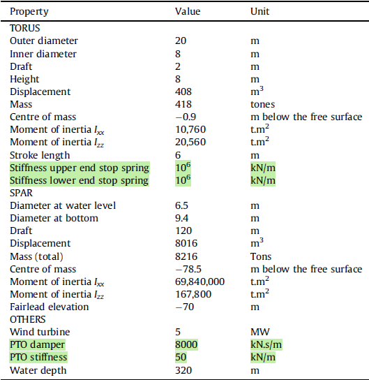
I am validating the results with respect to one benchmark paper, which has given some stiffness values, the problem I am facing is that, which value i need to adopt for the stiffness connection and fender connction, a picture related to the details provide in the paper is attached,I have highlighted the stiffness values, in that i have taken the PTO stiffness value for fender and stiffness upper/ lower end stop spring value used for the x-x, y-y in connection stiffness matrix, i am not sure wheather i have applied them correctly, and im not getting what values, need to be used for RX,RY,RZ in stiffness connection which i need to provide in N.m/degree. and regarding to fender option there is option for friction coefficient, damping coefficient, and stiffness coefficient, reffering to the aboce details, what value i need to adopt for them.
Please guide me with this.
-
July 30, 2024 at 9:59 am
Mike Pettit
Ansys EmployeeHello,
Just to clarify, are you only running a Hydrodynamic Diffraction analysis? Or are you also going to run a time domain Hydrodynamic Response analysis?
If you are performing Hydrodynamic Diffraction only, the results will provide you with the linear motion response (RAOs) of the spar/torus, which cannot consider the end stops. You can model the PTO stiffness using Connection Stiffness matrices, and you can apply additional damping to the torus. You can set very large values for the RX, RY, RZ stiffnesses to constrain the torus motion with respect to the spar. Any fenders you have defined under Connections will not be considered in the Hydrodynamic Diffraction analysis.
If you are performing a time domain Hydrodynamic Response analysis, you should create fenders at the end stop locations, with the fender stiffness set to the 'Stiffness upper/lower end stop spring' values. The fender sizes and positions should be defined so that there is a 6 m gap between the (uncompressed) fenders. For example, if the fender size is set as 1 m, the fender connection points should be located at +/- 4 m, so that there are 6 metres between the uncompressed fenders.
Mike
-
July 31, 2024 at 6:00 am
rohitshivalli22
SubscriberHi Mike,
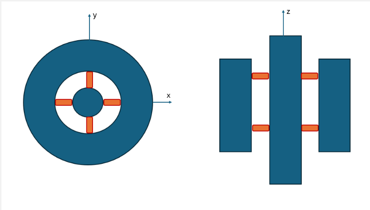
I am running both Hydrodynamic Diffraction and Hydrodynamic Response simulation,This is the arrangement of fenders that I have used for the spar and torus in time response analysis, and which type of fender do I need to use, to keep the relative motion between both the structures only in heave direction,
like I have used the fender as the floating kept the action in Z direction, or do i need to change it.

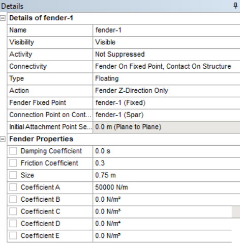
These are the values that I have used for fenders, 50000N/m for stiffness coefficient, and 0.3 for friction coefficient, I didn’t got what value need to be taken for damping coefficient, according to your last message do I need to adopt ‘Stiffness upper/lower end stop spring’ for the stiffness coefficient.
-
- The topic ‘how to create fender between two structures in hydrodynamic diffraction’ is closed to new replies.


- JACOBI Convergence Issue in ANSYS AQWA
- Two-way FSI simulation
- Ensight Force_per_unit area_EV
- RIBBON WINDOW DISAPPEARED
- Fluent Meshing Error when .dsco not .stp
- Ansys Fluent for modelling Ocean Wave reactions to Wave Barriers
- Battery Pack cooling
- ISAT ABORT error
- UNASSIGNED INTERFACE ZONE DETECTED FOR INTERFACE…

-
4597
-
1495
-
1386
-
1209
-
1021

© 2025 Copyright ANSYS, Inc. All rights reserved.


