We have an exciting announcement about badges coming in May 2025. Until then, we will temporarily stop issuing new badges for course completions and certifications. However, all completions will be recorded and fulfilled after May 2025.
Fluids

Fluids

Topics related to Fluent, CFX, Turbogrid and more.

Heat Flux applied on pipe wall

    • ziadkoussa
      Subscriber

      Hello


      I am trying to run a simple model that consists of an extruded circle (forming a cylinder). 


      The set up is such that a fluid flows through the interior of the cylinder/pipe and there is a heat flux applied on the wall. However, when I read the results for the Nusselt Number, I get incorrect values (compared to literature). When I set heat flux to 0 and set a higher temperature at the wall to simulate heat transfer, the curve for the Nusselt number is more representative of the values I should be getting. 


      How should I set up my model ?


      Thank You


    • peteroznewman
      Subscriber

      I suggest you build an axisymmetric model of a pipe.  I did a tutorial for Natural Convection of a hot pipe. You can adapt that to your needs.

    • ziadkoussa
      Subscriber

      Hello, 


      Thank you for your help 


      I think I've seen this video however I need to build a 3D model. 


      Please find attached pictures of my mesh. 


    • peteroznewman
      Subscriber

      Why do you need a 3D model? What boundary conditions do you have that are not axisymmetric?


      Is the flow laminar or turbulent?  Nusselt Number is all about the boundary layer. Your mesh does not have small enough element thickness at the wall.  Have you divided the pipe into an entrance length where the velocity profile is developing and a downstream length where the flow is fully developed?  Are you computing the heat transfer coefficient in the fully developed region, or including the entrance length?


    • ziadkoussa
      Subscriber

      My thesis advisor said my model must be in 3D


      My flow is laminar and for this case my pipe diameter = 5e-5m. 


      Find attached more details on my mesh, acquired velocity and temperature profiles, and how I am calculating nusselt number. 


    • peteroznewman
      Subscriber

      The three plots you show have no labels on either the x or y axis. I can't follow how you are calculating Nusselt number.


      Have you divided the pipe into an entrance length where the velocity profile is developing and a downstream length where the flow is fully developed?  Are you computing the heat transfer coefficient in the fully developed region, or including the entrance length?


      I recommend you do an axisymmetric model for yourself, even if you don't show it to your advisor. What are your advisor's reasons for requiring a 3D model?  It is foolish to build a more complicated model when a simpler model will give you the same (or better) information.

    • ziadkoussa
      Subscriber

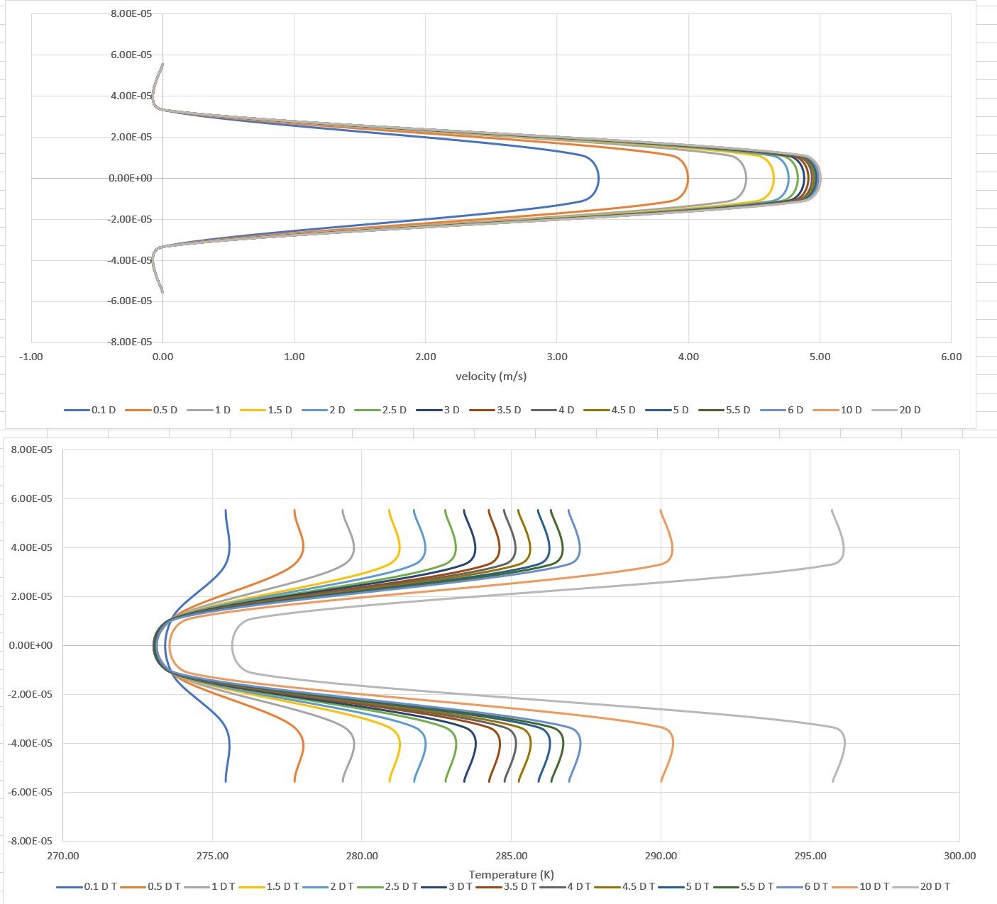
      the x axes are accordingly labelled as either temperature in K or velocity in m/s and the y axis for both are the radial length from the centre (these are temperature and velocity profiles for the cross sections)


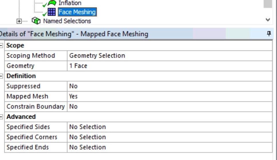
      and no the pipe has three named sections (velocity inlet, velocity outlet, and wall) and the HTC is including the entrance length. 


      from the graphs and calculations, the flow is fully developed after about 20 diameters so I will create a separate section there to measure the HTC from. However, the nusselt curve or HTC curve measures the nusselt number or HTC at each individual  axial length coordinate rather than the whole section. 


    • Rob
      Forum Moderator

      The HTC is based on a reference temperature: that's in the Reference Values in Fluent. You may be better off looking at the different HTC reports: the solver will be correct (if converged) but the reference may differ making comparison difficult. 


      Note, 50micron tubes are very small, so you may also be missing some physics in Fluent. This also assumes your experimental rig is accurate enough at this scale. 

    • atulsingh92
      Subscriber

      A side question here perhaps.@peteroznewmann
      If there is a periodic unit of a pipe lets say 11 mm (Not axis symmetric becuase I have a helical cut along the extrude length in the periphery of the pipe).
      How then should the nusselt number be interpreted?
      As the modeled pipe is only 11 mm long, of diameter 10 mm , the (x/D value is less than 10, Incropera-Dewitt Fundamentals of HMT), so there is no scope of developed flow here.
      In this case, if I am observing SHTC and Nusselt number,


      1) Which formula of Nusselt is being calculated by Ansys?
      2) What Nusselt value means here then?

      PS: I do have a BL which shows me Y+ < 2

    • Rob
      Forum Moderator

      Except the whole purpose of periodic flow means the "length" is infinite. Please keep questions to one thread: I'll lock this one to avoid confusion. 

    • Oussama Otman
      Subscriber

      Hello,

      Where can I find the models provided by the editor please ?

      Model A - Laminar flow through a pipe with uniform heat flux

      Model B - Natural convection in a concentric annulus

      Model C - Turbulent flow in a 90° pipe-bend

      Thank you !

Viewing 10 reply threads
  • The topic ‘Heat Flux applied on pipe wall’ is closed to new replies.