-
-
July 26, 2019 at 2:06 pm
mateusr
SubscriberHello everyone,
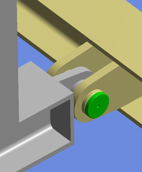
I have two metallic structures (Structure 1 and Structure 2) that are connected using a pin, as you can see in the image below.
My idea is to include some contact settings, saying that the face of the pin touches the padeye of structure 1 and also touches the padeye of structure 2. In this case, how is the type of contact to select?
The pin is also fixed axially in one of the structures (not possible to see how in the images), so how could I say to the software that the pin should remain fixed? Could I say that the head of the pin is bonded with one of the structures?
Thank you for your support.
-
July 26, 2019 at 2:33 pm
jj77
SubscriberUse frictional contact between the pin and all the surrounding surfaces parts that it is in contact with the outer surfaces of the pin.
Restrain the pin axially so it does not slide out - Supports/Displacements or Remote Displacement and restrain the direction you need.
-
July 26, 2019 at 2:34 pm
peteroznewman
SubscriberI suggest you suppress the pin solid body, and insert a Revolute Joint. Use the center hole for the Reference side and the outer holes for the Mobile side (or vice versa). The benefit is that the Revolute joint will not give you any convergence issues, but will provide a very similar connection between the two structures.
-
July 26, 2019 at 4:18 pm
mateusr
SubscriberDear Peter,
Thank you for your interest in this post. I did what you suggest using as a Reference Side the center hole of one structure and Mobile Side the center hole of the second structure and it works. But, if I want to leave the pins and understand what happen with them in the joint that I'm studying, can I still use a Revolution joint somehow?
-
July 26, 2019 at 4:29 pm
mateusr
SubscriberDear jj77,
Thank you for your interest in this post. Your idea is interesting and I'll try to implement it.
Regarding the two structures, there is small tolerance in between the lateral surfaces of padeyes (see image below). At the first moment they do not touch each other, but after the load, the surfaces can touch and movement is limited. Do you know how can I simulate this?
-
July 26, 2019 at 8:24 pm
peteroznewman
SubscriberIf you are interested in detailed stress in the pin, then do as jj77 said and use frictional contact. In that case, do not use a Revolute joint at all.
You can add frictional contact between the lateral surfaces of the padeyes to control the position of one structure to the other axially along the pin.
-
- The topic ‘Modelling Pin Joint’ is closed to new replies.


-
4633
-
1535
-
1386
-
1225
-
1021

© 2025 Copyright ANSYS, Inc. All rights reserved.


