-
-
May 20, 2024 at 8:43 am
ZHAO Te
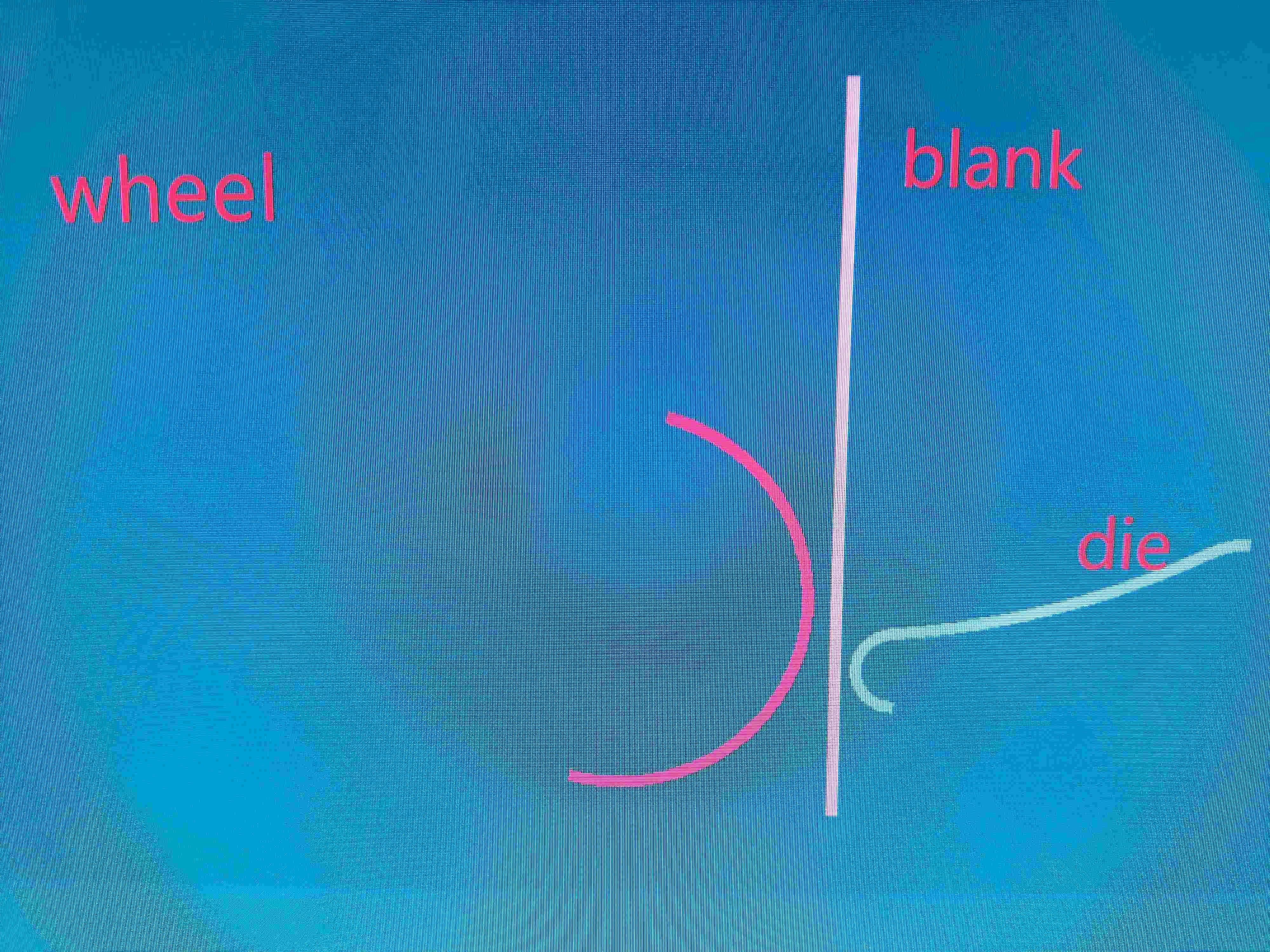
SubscriberCurrently, I am working on metal sheet metal forming. (Spinning) The sheet metal is in a normal state at low speeds, but at high speeds, 1. The sheet metal will float. There is another phenomenon, 2. When the spinning wheel touches the sheet material, it will take advantage of it as if there is a lot of kinetic energy. How to solve it


-
May 23, 2024 at 6:28 am
Reno Genest
Ansys EmployeeHello Zhao,
I don't understand the problem. Could you try to explain the problem in more details? Also, could you post a .gif showing the problem in a small animation? The limit for inline images and .gif is 1MB on the Ansys Forum.
Also, note that Ansys employees are not allowed to upload and download files on the Ansys Forum. But, you can upload your model and a video showing the problem and maybe another user will be able to help you.
If you are a commercial customer, please create a support case on the Ansys Customer Support Space and we will be able to help you better:
customer.ansys.com
Let me know how it goes.
Reno.
-
May 23, 2024 at 12:59 pm
ZHAO Te
SubscriberI'm very sorry for not explaining this issue clearly.
Working condition: Blank and die are connected by *Constrained_EXTRA_NODES-SET. The blank is formed through multiple processing steps by wheel.There are some issues here.
SECTION A:
1、Normal circumstances:Rotating wheel speed 628 rad/min (100r/min), wheel feed rate 40mm//min. The following is the result of my simulation.
This is a normal phenomenon.
2、However, When I adjusted the speed of the die to 3140rad/min (500r/min), the wheel speed remains constant. After being in contact with the wheel for a period of time, the blank detached from contact with the spinning wheel and deformed itself.( Blank,-press down on his own) This is seriously divorced from the facts.
3、At that time, I thought the speed was given too fast, so I maintained a speed of 628 rad/min (100r/min), The wheel speed has been slowed down to 8mm/min. But there are still issues with situation 2, except that the amplitude of deformation of the sheet metal itself decreases.
4、At 500r/min, the blank showed outward drift, but the experimental blank did not show any outward drift. Why does this phenomenon occur ?
I want to know, Wheel, without putting pressure on Blank, What is the reason for Blank's own deformation. At present, I speculate on my own whether it is related to dynamic relaxation phenomenon.But this problem has been bothering me for a long time and has not been solved yet.
-
May 24, 2024 at 1:42 am
Reno Genest
Ansys EmployeeHello Zhao,
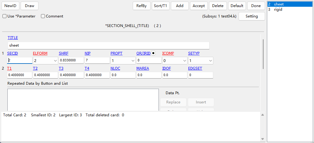
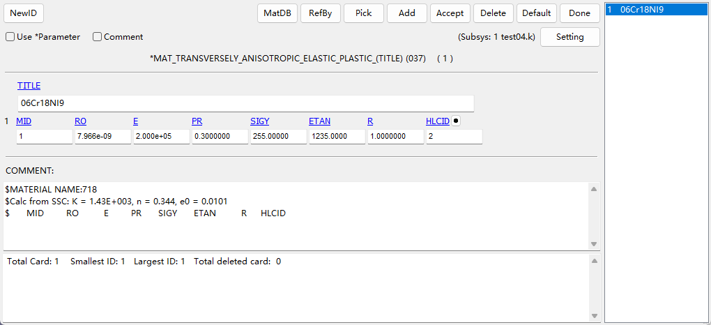
Which element type and elform are you using for the blank? Is it shell elements? Or solids? What material are you using for the blank? Do the element type and elform and material model for the blank remain the same when the rotating wheel speed is 628 rad/min and when it is 3140 rad/min?
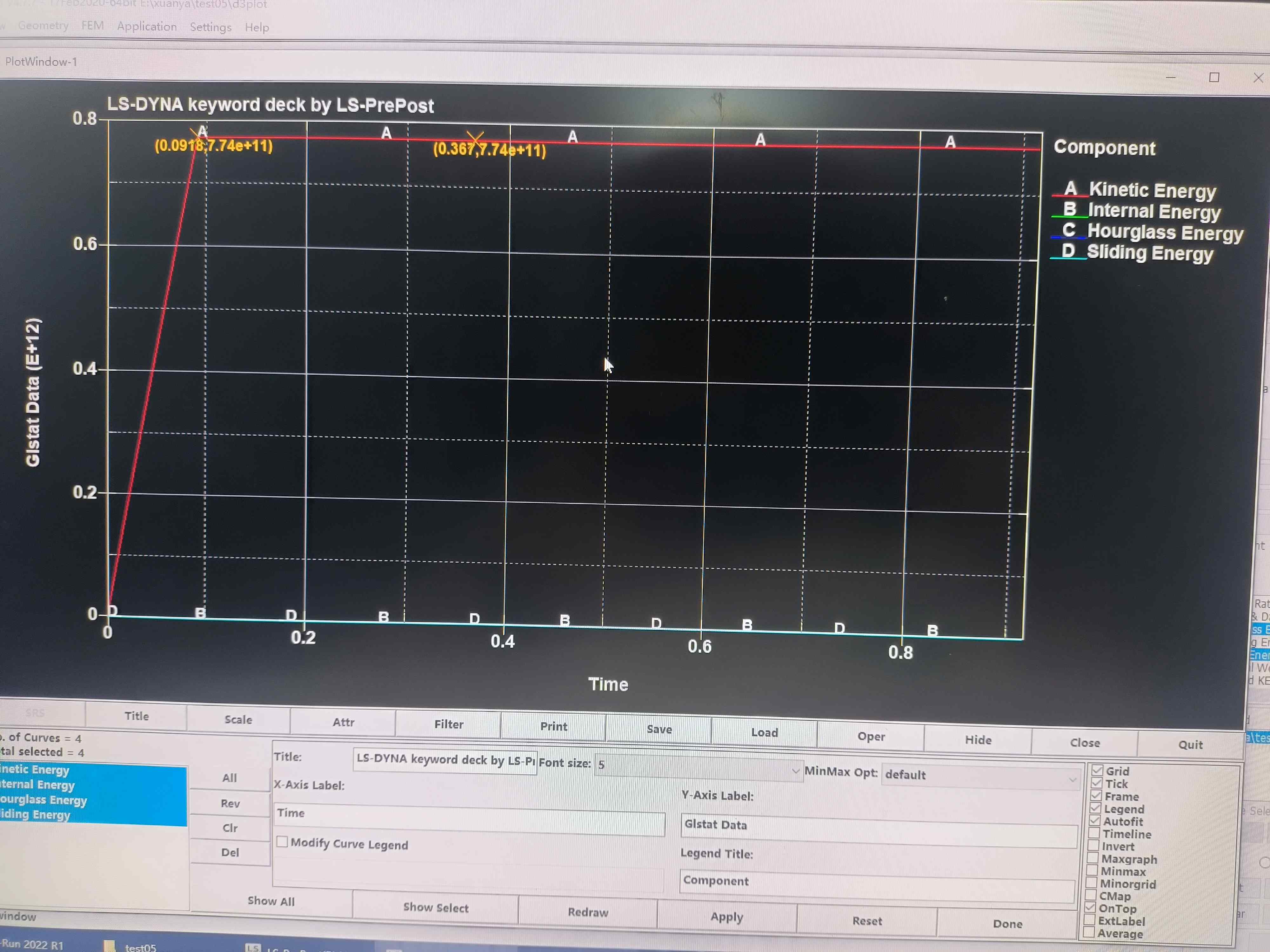
Have you checked your energy summary? Plot internal energy, kinetic energy, hourglass energy, and sliding energy together from the GLSTAT database and attach a screenshot here on this Forum post. Do you see any anomalies? Hourglass issue? Contact issue?
Is the wheel modeled as rigid?
Reno.
-
May 24, 2024 at 1:44 am
Reno Genest
Ansys EmployeeHello Zhao,
Also, which software are you using to post-process the results? And which explicit solver are you using for the forming simulation?
Reno.
-
May 24, 2024 at 2:47 am
ZHAO Te
SubscriberAll models are shell elements.
wheel modeled is rigid and no any anomalies
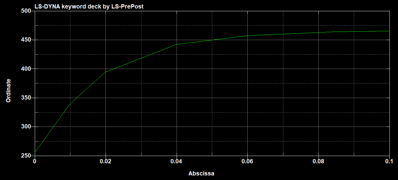
This is the material model.
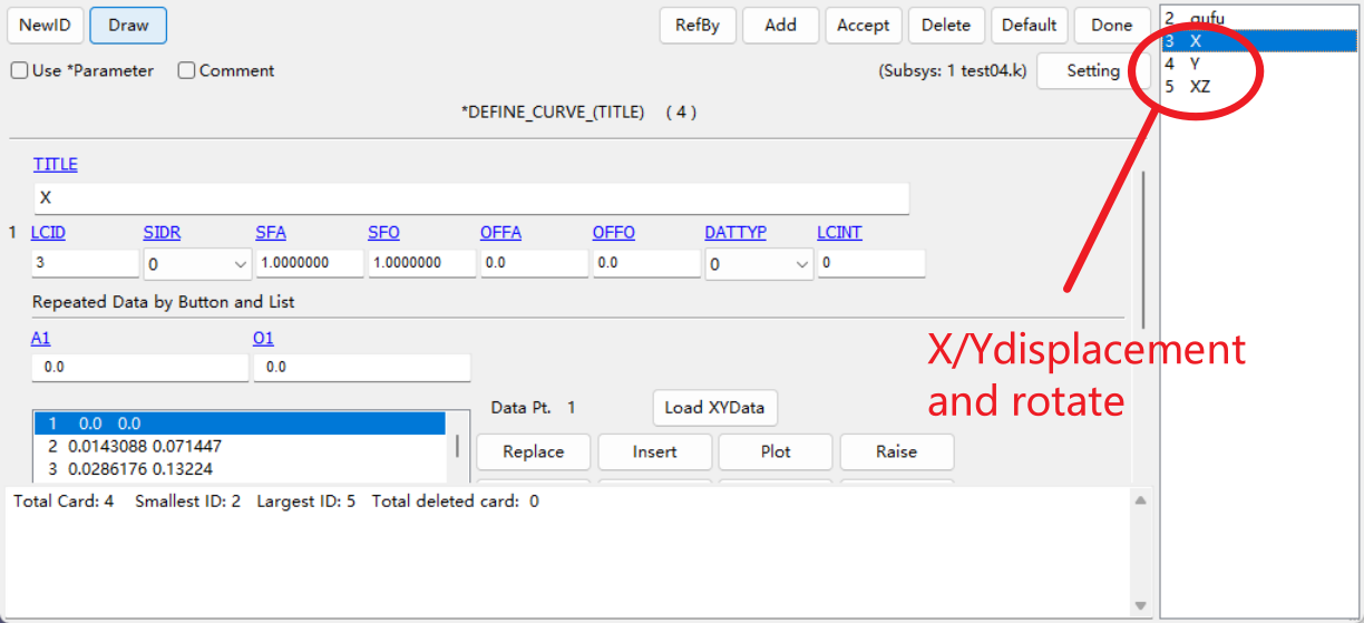
The element type and elform and material model for the blank remain the same when the rotating wheel speed is 628 rad/min and when it is 3140 rad/min. Only the rotating speed curve (situation 2) or the X/Y feed curve has changed.
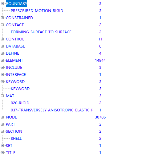
There are all keywords:
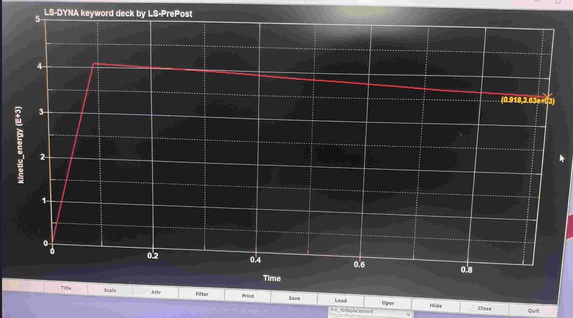
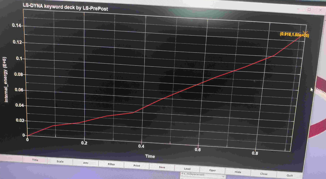
Energy issues:
situation 1(situation):
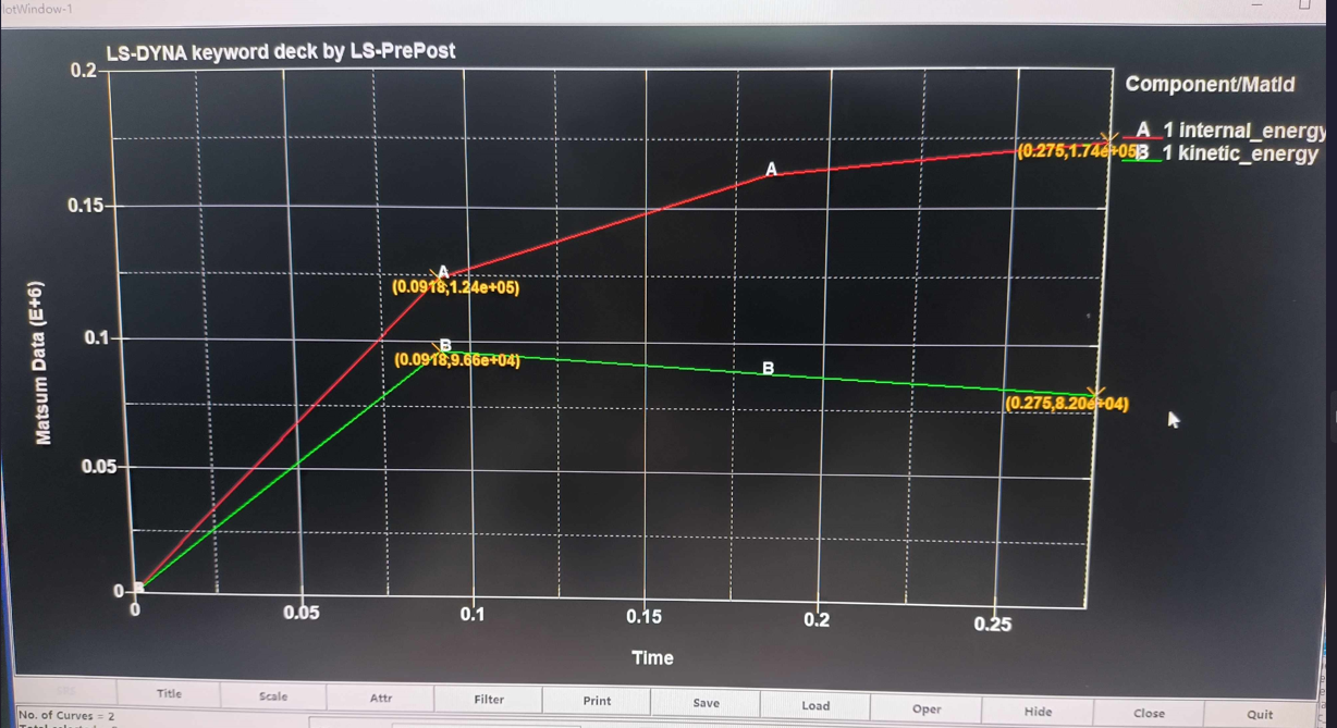
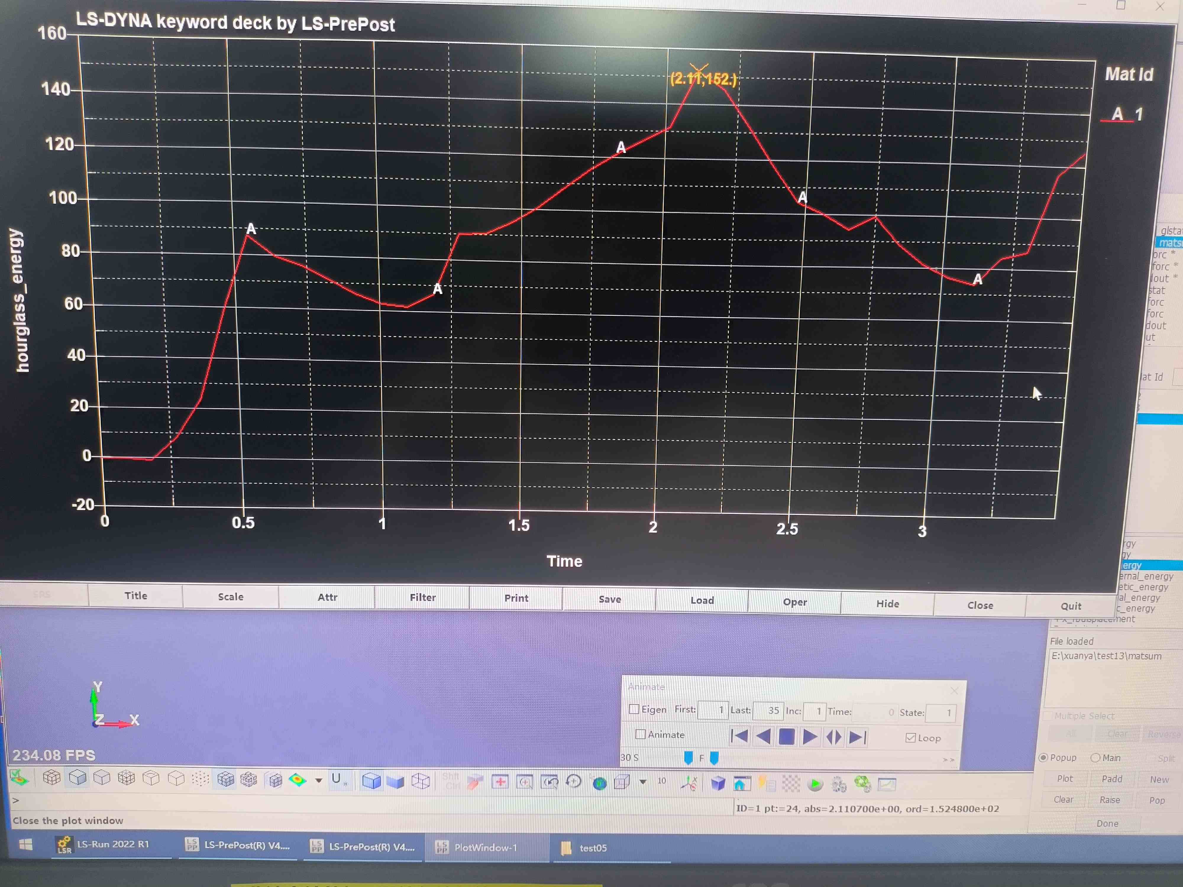
There are internal energy, kinetic energy, and hourglass energy from matsum (blank).
Kinetic energy, and hourglass energy are all no more than 5%.
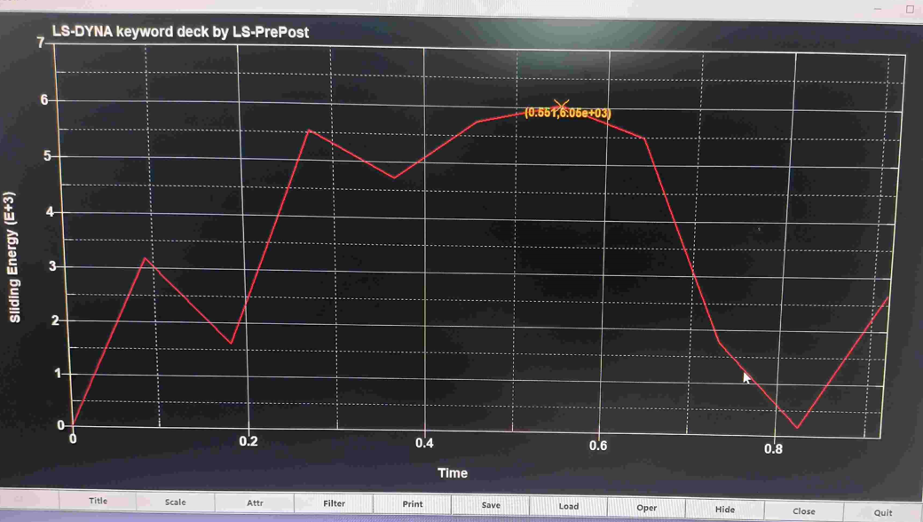
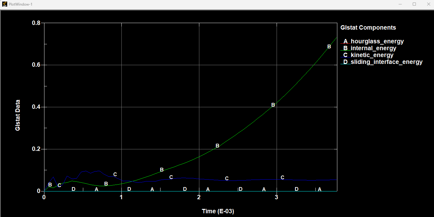
This is sliding energy from glstat.
But,I do not no how to judge.
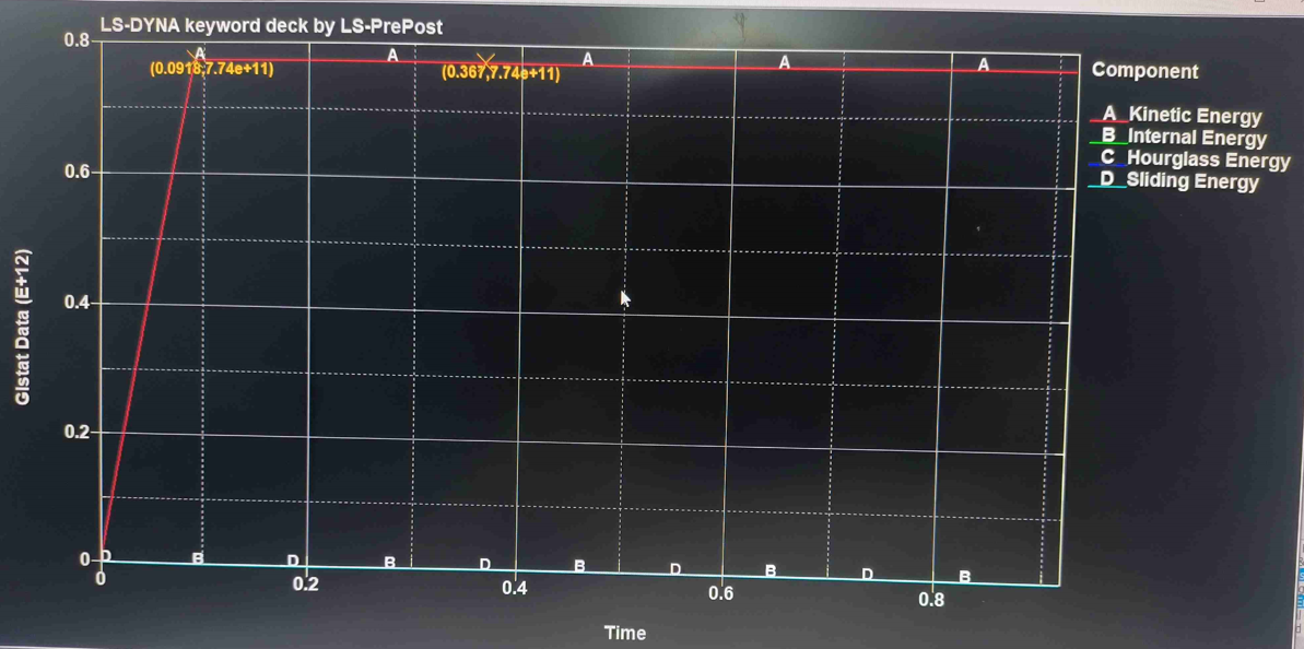
Situation 2(3140rad/min):
Perhaps due to the excessive rotational speed, the kinetic energy of the blank is too high, resulting in situation 3. Reduce the feed rate while keeping the rotational speed unchanged
Situation 3(100rad/min,feed rate 8mm/min):
Simultaneously refining the grid.
This has not been calculated yet, as it has shown a tendency for the sheet metal to deform downwards on its own.
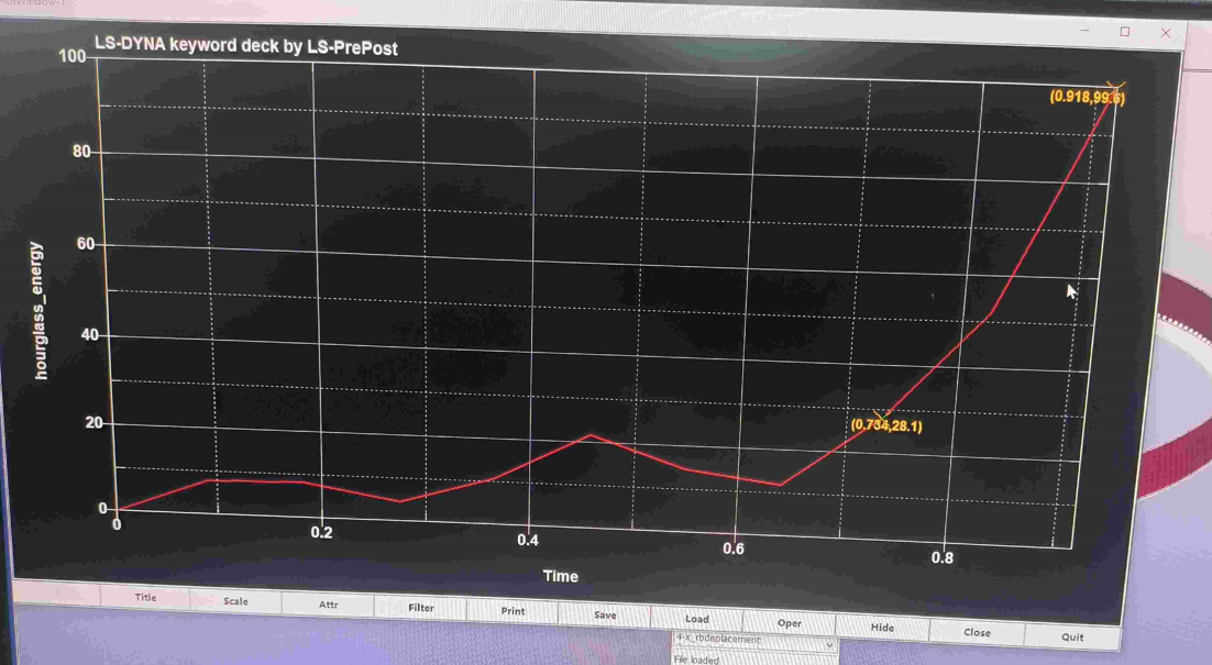
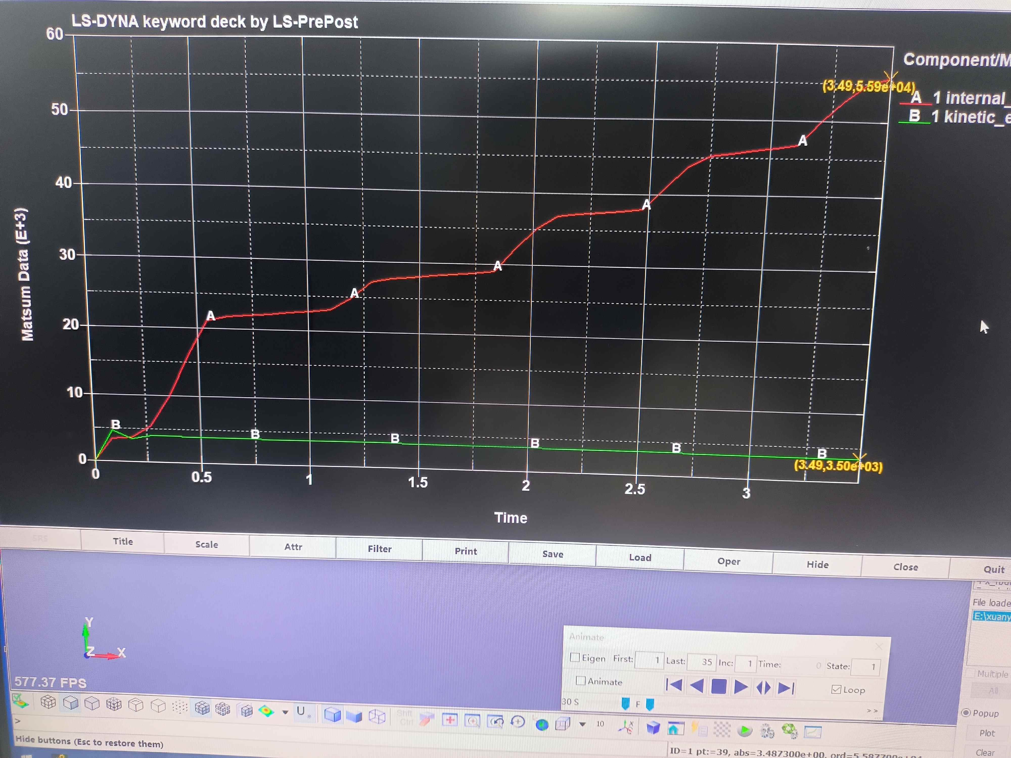
hourglass energy, and sliding energy :I found that the slip energy in situation three is very large. Is this the reason and how to solve it?
I use ls-run2022 for the forming simulation.
-
May 24, 2024 at 3:04 am
Reno Genest
Ansys EmployeeHello Zhao,
Try to plot all internal, kinetic, hourglass, and sliding energies on the same graph as follows:
In this case, I am using fully integrated elements and so hourglass energy is zero. Also, without friction, sliding energy should be zero, or less than 10% of internal energy. In the case above, the sliding energy is zero.
Have you tried with shell elform=-16 instead of 2 for the blank?
You may want to increase the NIP to have more integration points through the thickness of the shell.
At last, if contact energy is large, this could be the problem. You can post-process the contact force in the RCFORC database and compare the different cases. Is the contact force much larger when the wheel speed is increased? If so, then the contact may be causing issues. Maybe the speed of the wheel is so fast that some nodes on the blank penetrate the wheel. The speed of the wheel may be too high and the penetration is not detected. Then, the contact force applies a force proportional to the penetration distance times contact stiffness (Force = K * Dpene). This could lead to large forces being generated. You can fix this problem by decreasing TSSFAC on *CONTROL_TIMESTEP to reduce the timestep so that the nodes in contact don't penetrate too much. Another option is to reduce the bucket sort frequency number. See the LS-DYNA User manual for more information on bucket sort frequency. The bucket sort setting will change based on SMP or MPP and SOFT=0, 1 or SOFT=2.
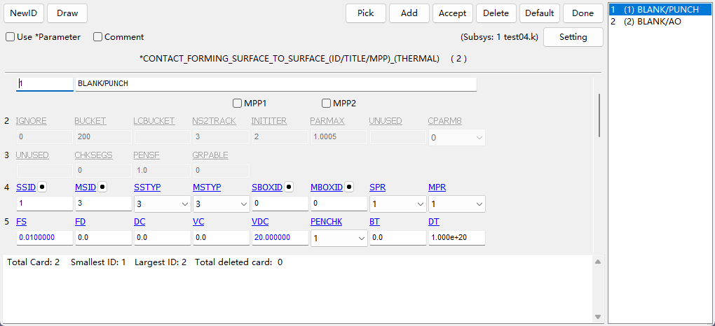
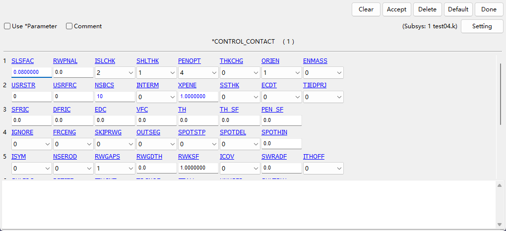
Note that changing the contact type and the SOFT option may solve this problem. Which contact are you using? Could you post a screenshot of your contact card with all options? The contact between the wheel and the blank.
Reno.
-
May 24, 2024 at 3:10 am
-
May 24, 2024 at 3:17 am
-
May 24, 2024 at 3:18 am
Reno Genest
Ansys EmployeeHello Zhao,
Yes, the wheel is probably spinning fast and this is why the kinetic energy is high. Try plotting only internal energy, hourglass, and sliding energies.
Reno.
-
May 24, 2024 at 3:21 am
-
May 24, 2024 at 3:22 am
Reno Genest
Ansys EmployeeHello Zhao,
The sliding energy and contact force should indicate if the contact is the issue or not. If the contact is the issue, try the following:
- I don't have much experience with forming contacts. But, I would try SOFT=2 (segment based contacts), SBOPT=3, and DEPTH=35. If it does not work better, try the *CONTACT_AUTOMATIC_SURFACE_TO_SURFACE with these settings instead.
- Reduce the bucket sort frequency.
- Reduce TSSFAC
Let me know how it goes.
Reno.
-
May 24, 2024 at 3:23 am
ZHAO Te
SubscriberI set my contact based on the spinning module of Dynaform
-
May 24, 2024 at 3:25 am
Reno Genest
Ansys EmployeeHello Zhao,
It is okay that the speed is fast in the experiment. We need to keep the same speed in the simulation and troubleshoot the problem :).
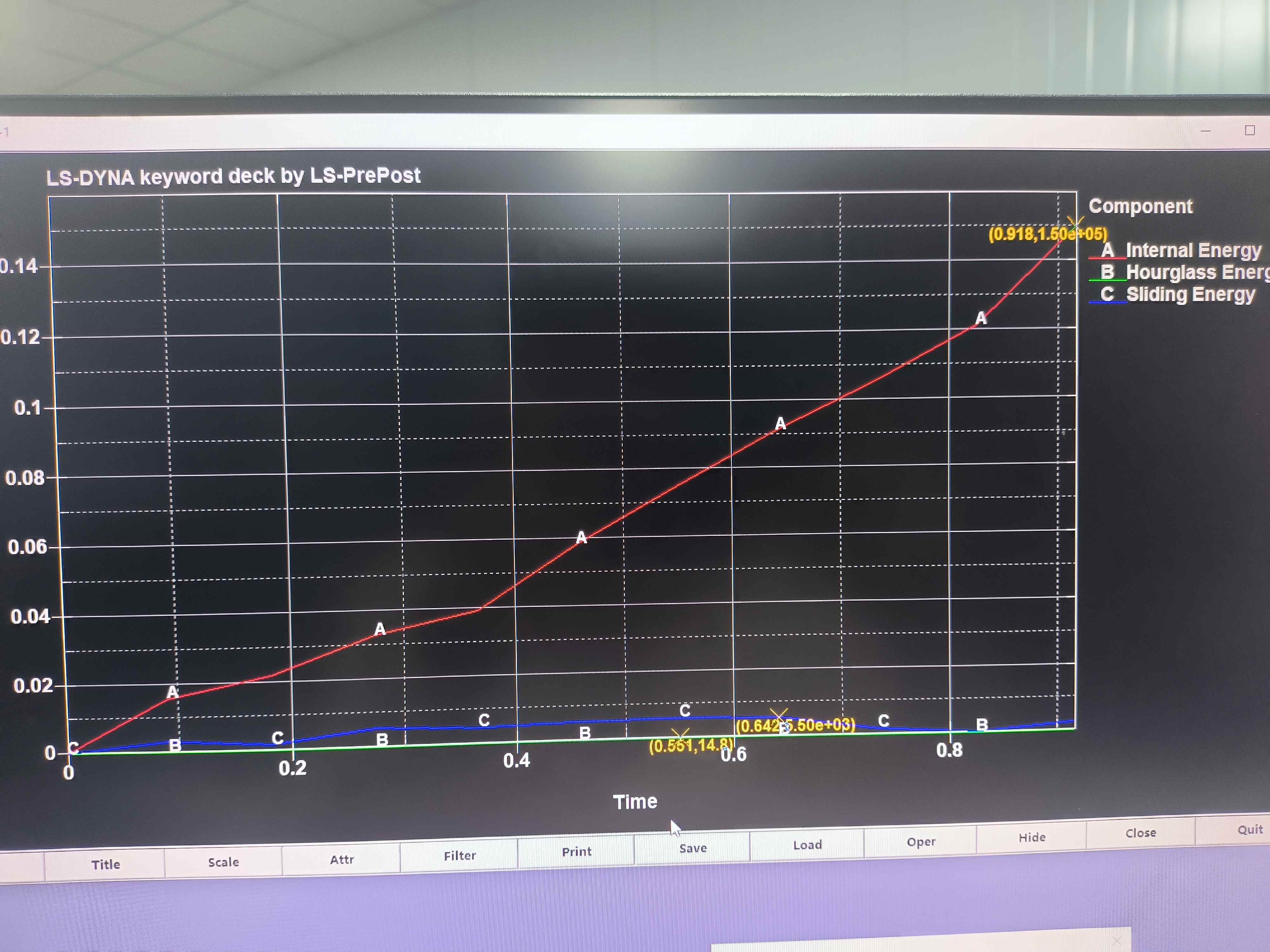
Plot the internal, hourglass, and sliding energy together on the same graph without kinetic energy. What does it look like? Please post a screenshot.
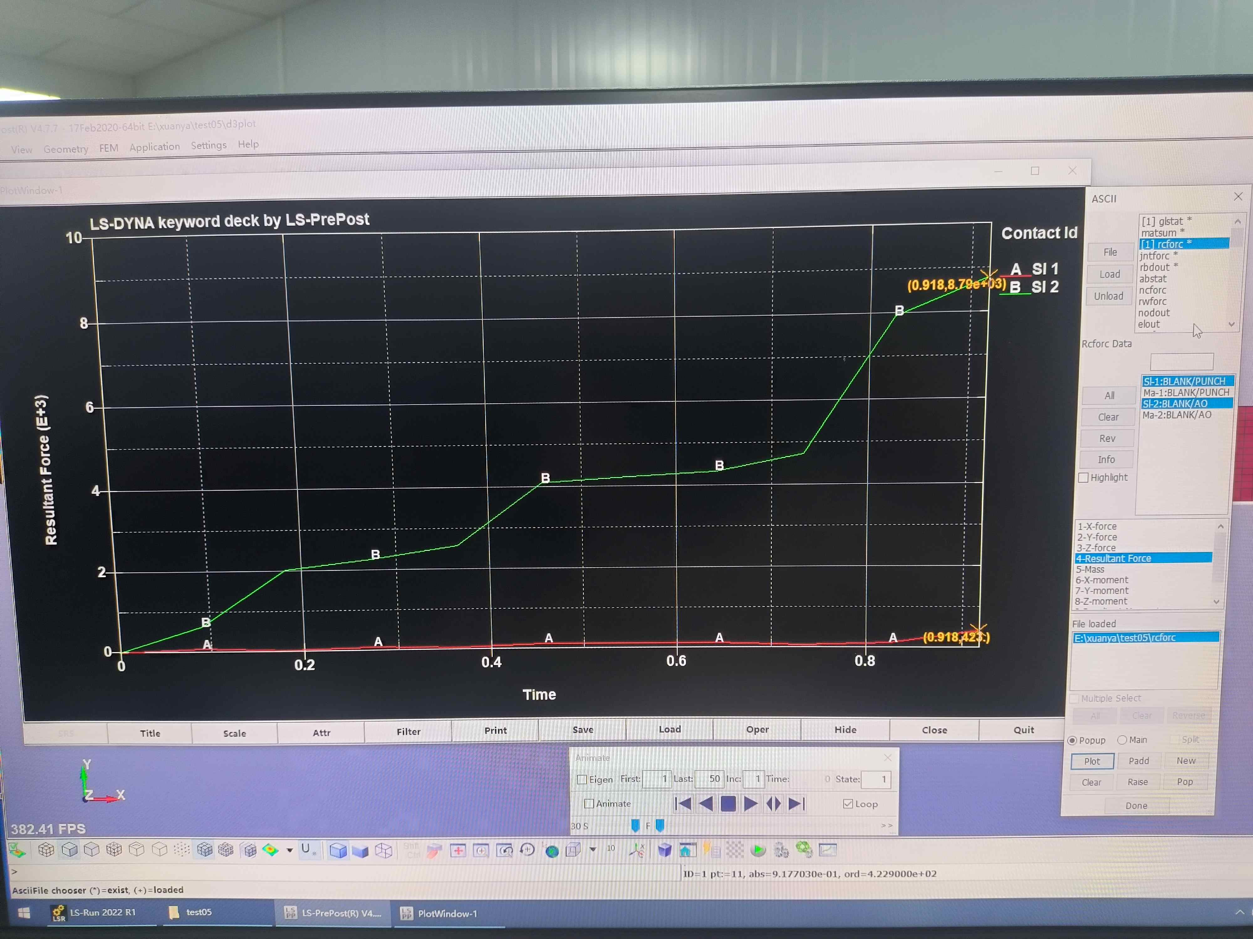
Also, check the RCFORC (contact force) between the blank and the wheel and compare between case 1 and 2. If the contact is the problem, the contact force should be much larger in case 2.
Reno.
-
May 24, 2024 at 3:26 am
ZHAO Te
SubscriberThank you ,I will make the modifications according to your suggestions and see how the situation is
-
May 24, 2024 at 3:27 am
Reno Genest
Ansys EmployeeHello Zhao,
Sounds good. Let me know how it goes.
Note that I will be on vacation starting now returning on Wednesday May 29.
Reno.
-
May 24, 2024 at 3:28 am
-
May 24, 2024 at 3:32 am
-
May 24, 2024 at 3:36 am
Reno Genest
Ansys EmployeeHello Zhao,
Your sliding and hourglass energies are less than 10% than internal energy. This seems okay. Is this the case for case 1 and case 2?
Could you compare the contact force on the same graph between case 1 and case 2? The contact force between the wheel (punch) and the blank.
Reno.
-
May 24, 2024 at 3:39 am
Reno Genest
Ansys EmployeeHello Zhao,
If you are a commercial customer, you can create a support case on the Ansys Customer Support Space (ACSS):
customer.ansys.com
This way, you will be able to send us the model and we will be able to help you better. We could also do a Teams meeting and share the screen for better model review.
Reno.
-
May 24, 2024 at 3:42 am
ZHAO Te
SubscriberThis is case 1. Case 2 kinetic energy is more than 10%.Case 3 sliding energy is 2.77e4, Internal energy is 5.59e4,Hourglass energy is 126. How can I reduce the sliding energy.
-
May 24, 2024 at 3:44 am
ZHAO Te
SubscriberI did not complete the calculation for situation 2, but the order of magnitude for CASE1 and CASE2 is the same
-
May 24, 2024 at 3:46 am
ZHAO Te
SubscriberI am a postgraduate.
-
May 24, 2024 at 3:47 am
ZHAO Te
SubscriberIn my confusion, thank you very much for your answer. I will work hard to modify the model and wish you a pleasant vacation,
-
May 24, 2024 at 3:54 am
Reno Genest
Ansys EmployeeHello Zhao,
If your research institution has commercial Ansys licenses, you can file a support case.
You can reduce sliding energy by trying the methods I explained before (SOFT=2, SBOPT=3, DEPTH=35), reduce TSSFAC, and reduce BSORT.
You will find more information on contact energy here:
Contact Energy — Welcome to the LS-DYNA support site
And more information about contacts in general here:
Intro-to-Contacts.pdf (oasys-software.com)
I like the above seminar from our channel partner Arup.
If you increase the d3plot output frequency, you might be able to see the contact problem. I suspect node penetrations that is not detected leading the larger forces on the blank.
Let me know how it goes.
Reno.
-
May 24, 2024 at 4:25 am
ZHAO Te
SubscriberThank you, I have tried to modify the model!!!
-
- The topic ‘Metal forming (spinning)’ is closed to new replies.


-
4763
-
1565
-
1386
-
1242
-
1021

© 2026 Copyright ANSYS, Inc. All rights reserved.

