-
-
May 8, 2024 at 6:28 am
Syamantak Das
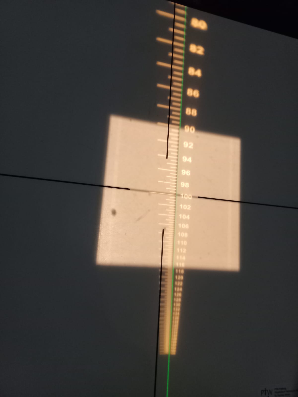
SubscriberWe want to simulate "Optical Distance indicator(ODI)". It consisits of a lamp( may be a point source), an aspheric condenser lens, a reticle( a scale grooved with diffrent thickness) and lastly a projection lens. The whole system will project the image of the reticle/scale to some other distance from where we can read the distance marked on the reticle.
How to simulate this whole system? Kindly help us.
-
May 9, 2024 at 6:01 am
Niki Papachristou
Forum ModeratorHi Syamantak,
Thank you for reaching out to us! I would suggest you to explore Zemax Optics Studio Sample files (there should be in your installation folder). One of the examples I can think of which is close to what you are describing is the Digital projector flys eye homogenizer: Using the OpticStudio Non-Sequential Optimization Wizards
I hope that was helpful, let me know if I can be of further assistance!
Kind Regards,
Niki
-
May 10, 2024 at 11:32 am
Syamantak Das
SubscriberHi Niki,
Thanks a lot for your support. We understood that we can construct a lamp( source), ashpheric lens and may be the projection lens. But we are struggling with the design of reticle/scale. A typical reticle generally has major scale marks at 1 cm intervals with minor marks every 0.5 cm. How to model this kind of scale using opticstudio as the object. We want to illuminate this scale/reticle to get the image of the retilce at some distance.
Please go through the following images. The setup( as attached above) will be mounted at an angle of 45 degress and we want the image of the reticle at some predefined distance.
The left image denotes the final image of the reticle at some distance. The right image shows the placement of ODI setup at 45 degree. The Left image will be obtained at the isocentre plane as denoted.
We are struggling to simulate the whole optimized system, as required. Kindly help us.
Thanks
Syamantak
-
- The topic ‘Simulation of a whole optical system for Optical Distance Indicator’ is closed to new replies.


-
4613
-
1520
-
1386
-
1209
-
1021

© 2025 Copyright ANSYS, Inc. All rights reserved.


