-
-
July 17, 2019 at 2:48 pm
user deleted
SubscriberHello!
I try to conduct a simulation in Ansys Fluent and I faced with the problem:
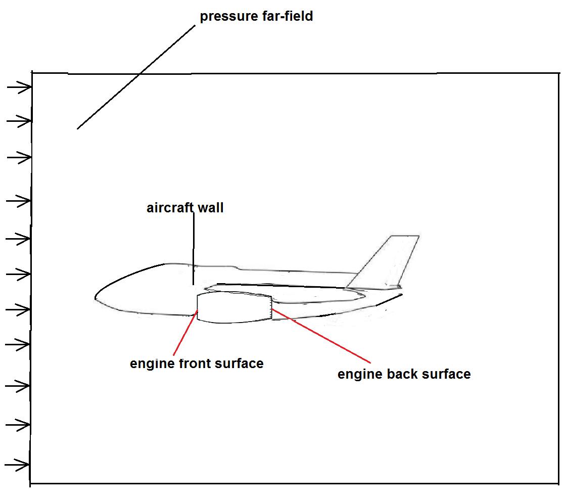
I conduct the aerodynamic simulation for turbo jet airplane. And I don't understand how to set boundary conditions in engine inlet and outlet. I know mass flow (kg/s) for inlet and outlet and operating conditions. I have tried to set mass flow-outlet at the engine inlet and pressure outlet / mass-flow inlet at the engine outlet, but the convergence was not good.
Could you please give me some advises?
Have a nice day!
Many thanks and best regards,
Katiya
Â
-
July 17, 2019 at 3:52 pm
Rob
Forum ModeratorIf the engine is a void (ie the ends are represented by surfaces) you can suck flow out of the domain & blow it back in using mass flow boundaries.Â
-
July 17, 2019 at 5:03 pm
user deleted
SubscriberI set the mass flow outlet - at the engine front surface and mass flow inlet - at the engine back surface:
But in the result I have divergence and solution does not converge as far as it goes. Is it correct setting of boundary conditions?
Could you please recommend tutorials or any materials that could help me?
Many thanks and best regards,
Katiya
-
July 18, 2019 at 8:57 am
Rob
Forum ModeratorDo you have cells in the middle? If so you can't set the in & out flow rates as they'll never balance (domain will be vacuum or infinite density). Set the inlet as mass flow (use velocity inlet if density is constant) and outlet as pressure.Â
-
July 18, 2019 at 10:02 am
user deleted
SubscriberThere are two types of mass flow: "mass-flow-inlet" or "mass-flow-outlet"? What is correct?
Do you recommend at the back surface use "pressure outlet"?
Many thanks and best regards,
Katiya
-
July 18, 2019 at 10:39 am
Rob
Forum ModeratorDepends: is the flow going into the domain or out of the domain? If you click on "help" in the solver in R19.x or 2019Rx you'll be able to navigate to a set of tutorials, I'd advise going through some of these to understand what/why/how before working on your case.Â
-
July 18, 2019 at 12:56 pm
user deleted
SubscriberIn case if the flow going in the domain I should set "mass-flow-inlet"?
Thank you, I will try it!Â
Many thanks and best regards,
Katiya
-
July 18, 2019 at 1:34 pm
Rob
Forum ModeratorIf you're just modelling the duct it's usual to use a mass flow inlet & pressure outlet: you may also need to include some of the engine innards. If the unit is attached to a wing and you're modelling the rest of the aircraft and surrounding region it's more complicated and you really need to describe what you're doing (with images).Â
-
July 18, 2019 at 5:16 pm
user deleted
SubscriberI conduct simulation for turbo jet airplane. The boundary conditions are depicted below:
The flow direction is showed by arrows. I don't understand what boundary condition should be apllied at the front and back engine surfaces. I tried different combinations, but the convergence was awful.
Could you please help me?
Many thanks and best regards,
Katiya
Â
-
July 19, 2019 at 8:53 am
Rob
Forum ModeratorOK, that makes more sense. You need a pressure far field all around the domain, and (I hope) a lot more space around the aircraft. For the engine use a mass flow outlet (engine intake) and mass flow inlet (engine exhaust). There is no cell zone inside the engine: I've seen a paper covering jet fans for tunnels using this approach with Fluent but it may have been hardcopy rather than on-line.
-
July 19, 2019 at 5:16 pm
user deleted
SubscriberI tried to set such conditions, but there was no convergence. I don't know how to fix it. Could you please recommend something?
Many thanks and best regards,
Katiya
Â
-
July 22, 2019 at 12:20 pm
Rob
Forum ModeratorWork through the mesh (cell shape quality, growth rate & resolution) then onto the settings. Please post a plot of the residuals.Â
That configuration will work but "not converging" covers a lot of potential issues.Â
-
- The topic ‘Boundary Conditions for Turbo Engine’ is closed to new replies.
-
5054
-
1764
-
1387
-
1248
-
1021
© 2026 Copyright ANSYS, Inc. All rights reserved.

