TAGGED: #mechanical-#workbench
-
-
April 28, 2024 at 8:12 am
Jaewook Lee
SubscriberHello.
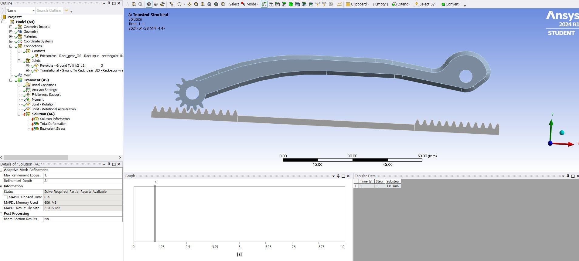
I would like to proceed with the above interpretation of rack and pinion gear.
My goal is to interpret the load applied when a certain amount of torque is applied to the pinion gear. However, the interpretation did not go well.
There are two major problems.
1. As the angle of rotation of the gear increases, an analysis error occurs. This seems to be a problem caused by the fact that the gear teeth in contact with in the initial state are no longer in contact by rotation. In order to solve this problem, we tried to change the contact condition from bond to frictionless or rope, but in this case, an error occurred regardless of the angle of rotation.2. Rotation does not occur when moment conditions are entered into the pinion gear.
Do you know how to solve these two problems?
Because I used a translator, the expression may not be appropriate.
-
April 28, 2024 at 10:21 am
peteroznewman
SubscriberI see a large gap between the gear teeth. That is bad. The gear teeth should be touching before the analysis begins. Create better gear teeth geometry.
-
April 28, 2024 at 2:18 pm
Jaewook Lee
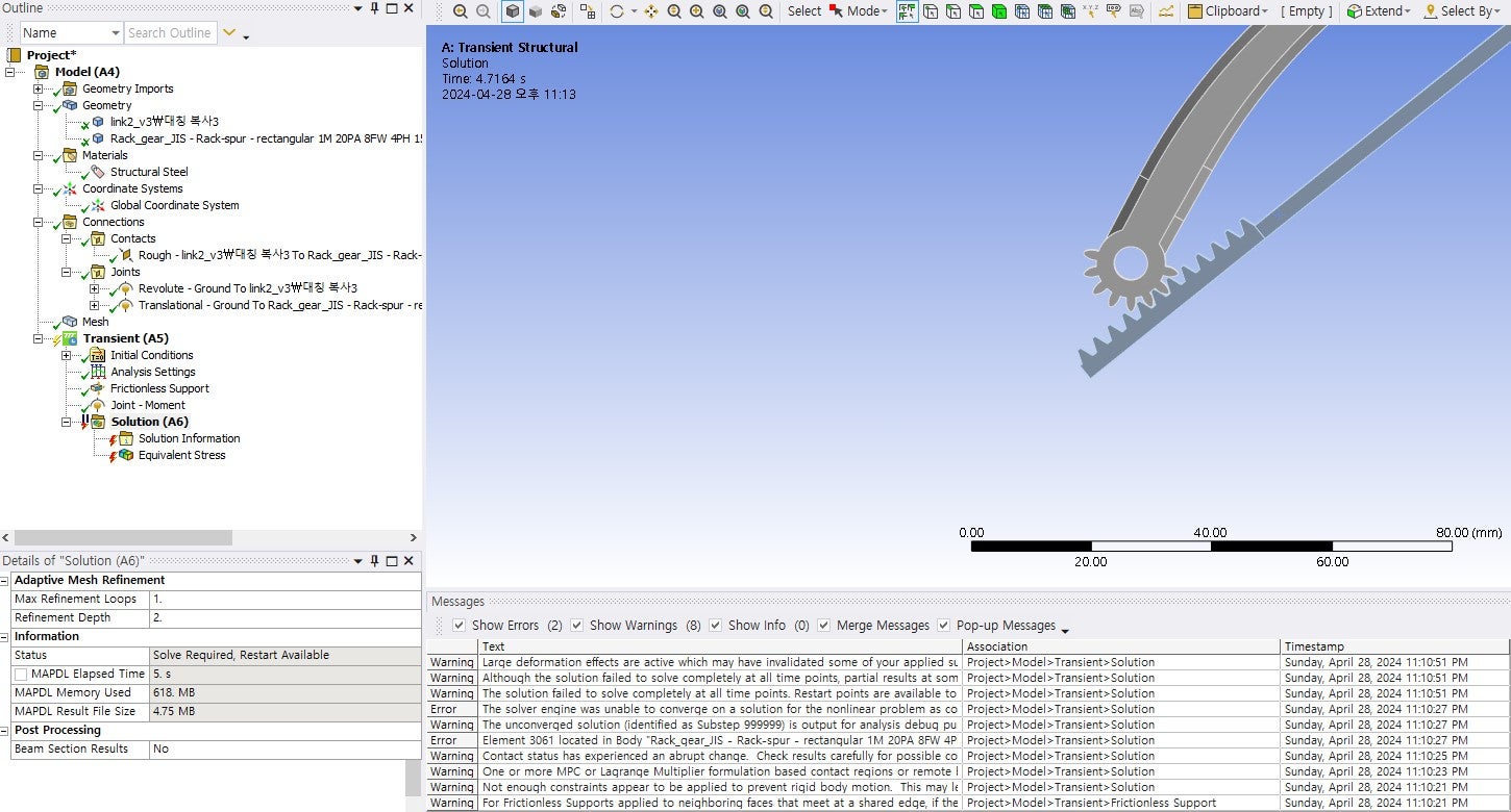
SubscriberThe gear position was adjusted and the analysis using angular acceleration was successful. However, the analysis does not proceed even if the moment condition is still given. I tried to give it as a joint-moment condition after selecting the revolving joint surface set on the pinion. The picture below shows the errors that occurred in the analysis. What did I make a mistake?

-
-
April 28, 2024 at 10:02 pm
peteroznewman
SubscriberWhat are the Analysis Settings? Especially the Initial, Minimum and Maximum Timesteps?
What face was used for the Translation Joint?
What face was used for the Revolute Joint?
What does the mesh look like?
Under the Solution Information folder, show the Force Convergence plot.
Under the Solution Information folder type a 3 for the Newton-Raphson Residual Plot and a 3 to show the Element Violations. After you solve with those numbers entered, there will be a Named Selection that shows the Element listed in the Error. Show where that element is.
-
- The topic ‘Rack and pinion analysis’ is closed to new replies.


-
4858
-
1587
-
1386
-
1242
-
1021

© 2026 Copyright ANSYS, Inc. All rights reserved.


