-
-
April 25, 2024 at 9:03 pm
Adeleine Cabrera
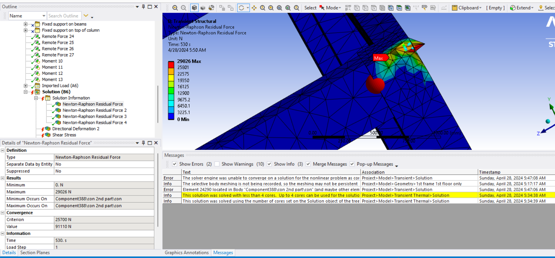
SubscriberHi. I'm analyzing with transient structural analysis. The large deflection is turned on. I want to check the moment reaction on the red area shown below using a moment probe. But, the resulting moment is at the centroid of the body and not at the centroid of the surface. And, the moment is very large. The displacement is only around 8mm.
Can someone explain me how to get the moment reaction at the surface only? And if there's something I may be doing wrong for the moment reaction to be this large? And how does the resulting moment be placed at the centroid of the body and not on the surface?
Thank you.Also this is the force reaction at that surface, for reference:

-
April 26, 2024 at 11:02 am
peteroznewman
SubscriberHi Adeleine,
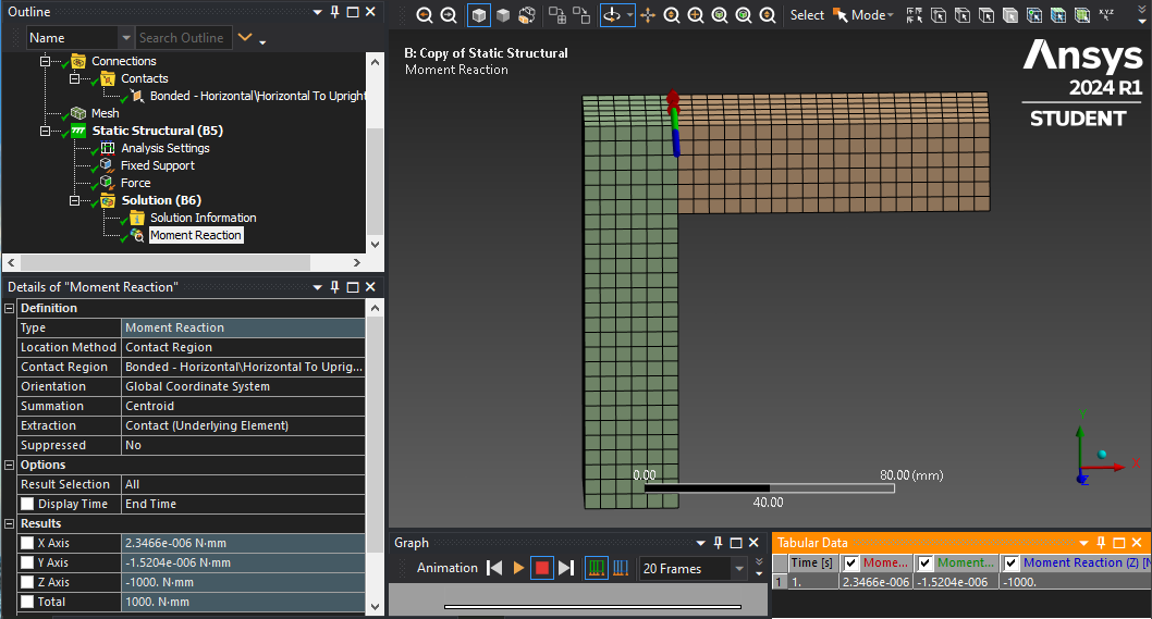
When bodies have a Bonded Contact, the Moment Reaction at the Bonded Contact comes out at the expected value. I modelled a 100 mm horizontal beam with a 10 N vertical force and get the expected 1000 N.mm Moment on the Bonded Contact Region.
It looks like the bodies in your model are connected using Shared Topology. When you do this, the Moment Reaction comes out at zero.
-
April 26, 2024 at 3:39 pm
Adeleine Cabrera
SubscriberHi. May I ask an explanation why using shared topology results to zero moment? I thought the main difference between using contact and shared topology is that shared topology makes the meshes between bodies contect.
-
April 27, 2024 at 12:45 pm
peteroznewman
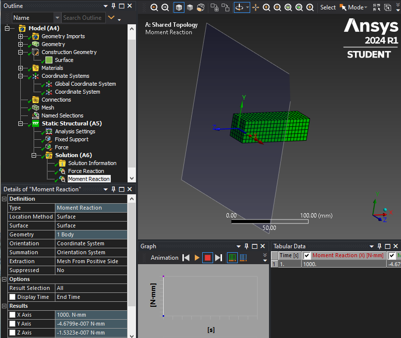
SubscriberHere is how you can get the moment from any mesh regardless of where in the mesh you want the data.
- Create a coordinate system where the XY plane is where you want it to cut through the mesh.
- Create a Construction Geometry surface using the coordinate system from step 1.
- Under Analysis Settings, Output Controls, turn on Nodal Forces and Solve.
- Insert a Moment Reaction and set it as shown below.
The sum of the forces from the elements attached to each internal node is zero. Only nodes at supports or applied loads have a non-zero sum of forces on them. Using the above method, you can tell the Moment Reaction tool which elements to use to do the summation: positive side of the mesh or negative side, and by summing only forces on one side, you end up with a non zero sum because if you sum elements on both sides, the answer is zero.
The problem with chosing a face in the Shared Topology model is that face is shared between two bodies, so when it uses the elements from both bodies, it calculates the correct answer of zero.
-
April 27, 2024 at 9:53 pm
Adeleine Cabrera
SubscriberHi. Thank you. I followed these steps and got a result. However, the moment probe gave a very large moment. I'm going to transfer this moment result to another frame. But when this large moment was applied to the other frame, the force and displacement doesn't converge and, it looks like the problem is the applied large moment. I've tried making the surface to have a finer mesh and increasing the substeps but none worked. Do you have any tips?

-
April 28, 2024 at 12:17 pm
peteroznewman
SubscriberHi Adeleine,
It looks like the beams have about a 300×300 mm section.
I recommend you place a Csys about 600 mm away from the joint so that it cleanly cuts through the beam. Request the Reaction Force through that plane. To transfer that force to another frame, create the same 600 mm long stub and apply that Reaction Force the end face. Assuming this model converges, you should ignore the stress in the stub near the cut end as it may show some disturbance from the cut boundary.
Transferring forces is cleaner than moments because the force is directly applied to nodes and as long as the coordinate frames have X, Y and Z pointing in the same directions in each model, the transfer will be correct. Moments can’t be applied to nodes on solid elements, they have to be converted to forces first. The problem is if the origin of the coordinate system with respect to the cut face is not identical between the two models, the conversion of moments to force can introduce a huge scale factor error. This can’t happen when forces are transferred.
-
November 19, 2024 at 12:46 pm
dmitrii.matias
SubscriberHi Peteroznewman,
could the above described problem be potentially related to a flaw which consist of ANSYS wrongly calculating the moment in case when Large Deflections are tuned on? As I understand, to compute the moment, ANSYS multiplies forces in nodes by distance from these nodes to the coordinate system or summation point (depending on what you have requested) related to UNDEFORMED shape (same applies when extracting from geometry region, contact region or construction surface). As a result, if you apply only force as boundary condition to some face and this face has experienced substantial deformation, you will also retrieve moment from this face even if no moment is applied. This could lead to wrong estimation of, for instance, loads on bolt heads, if this bolt connects model parts that by design should move considerably under loading.
More insights backing my points can be found in this post.
-
-
- The topic ‘Moment Reaction is large when large deflection is turned on’ is closed to new replies.


- LPBF Simulation of dissimilar materials in ANSYS mechanical (Thermal Transient)
- Simulate a fan on the end of shaft
- Nonlinear load cases combinations
- Real Life Example of a non-symmetric eigenvalue problem
- How can the results of Pressures and Motions for all elements be obtained?
- Contact stiffness too big
- Test post on Forum – LLM response – SC
- 13-Node Pyramid Element Shape Function
- Element Birth and Death
- Python-Script to Export all Children of a Solution Tree

-
4502
-
1494
-
1376
-
1209
-
1021

© 2025 Copyright ANSYS, Inc. All rights reserved.


