-
-
April 24, 2024 at 5:13 pm
Ken Ng
SubscriberHi,
I am working on a cylinder shape frictional surface trying to fit it with the experimental data. However, my model can't give me satisfying results.
the friction coefficient is set to 0.3 and below is my command
et, cid, 174
RMODIF,cid,21,5.3
RMODIF,cid,22,4
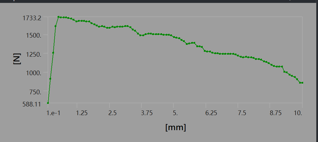
Initially, I used a mesh resolution of 0 (approximately 8mm), which resulted in a response that deviated from the expected exponential decay. In an attempt to improve the accuracy, I increased the mesh fineness.
Here I used a mesh resolution of 1 (approximately 6mm)
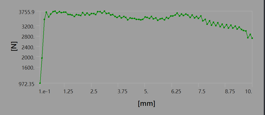
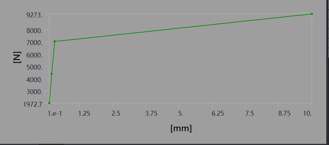
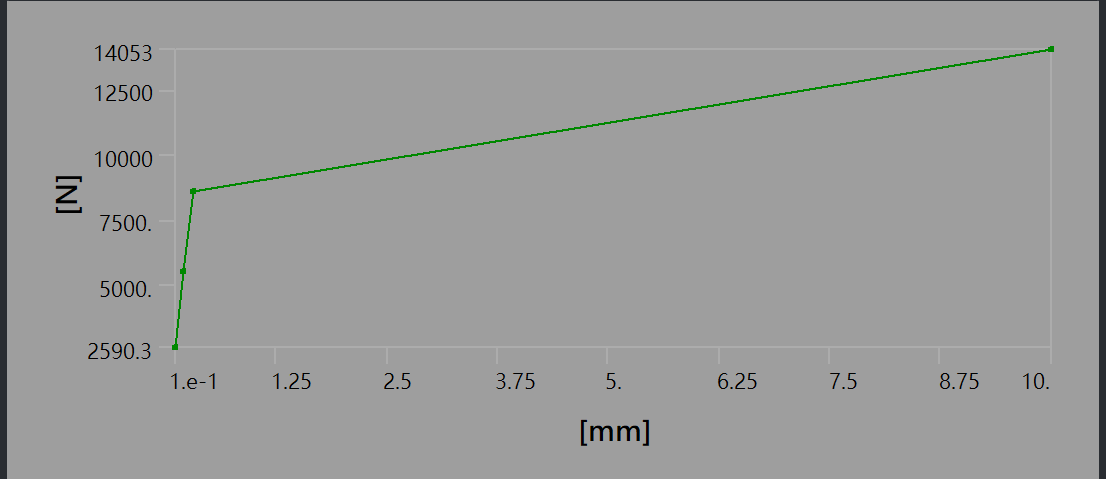
However, the challenges arose when I attempted to further refine the mesh size. Specifically, when the mesh resolution was set to 2 (approximately 4mm) or higher, I encountered an error message and obtained results that were unexpected.
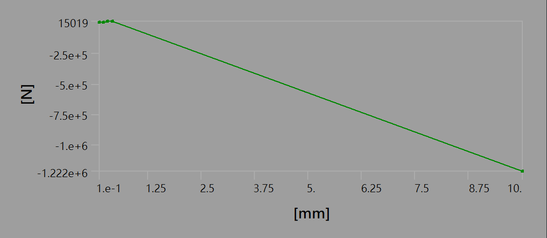
here is the result of mesh resolution = 3 ( about 3mm)
here is the result of mesh resolution = 4 (about 2.25mm)
I wonder if my command is incorrect or if I may mess up with other things that I can't run the simulation properly. Why the simulation is able to run in coarse mesh but not in fine mesh?
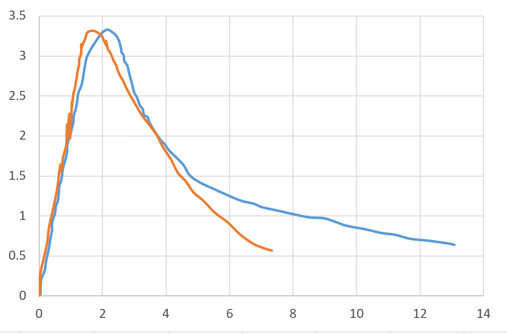
and what else I may need to set to make my simulation fit this orange line.
Thank you
-
April 25, 2024 at 10:47 am
Avnish Pandey
Ansys EmployeeHi Ken,
Can you share the images of the:
- contact settings for the frictional contact of your model
- analysis settings of your model
The solution is not converging and what is the intention behind adding the command snippet?
-
April 25, 2024 at 11:26 am
Ken Ng
SubscriberHi Avnish,
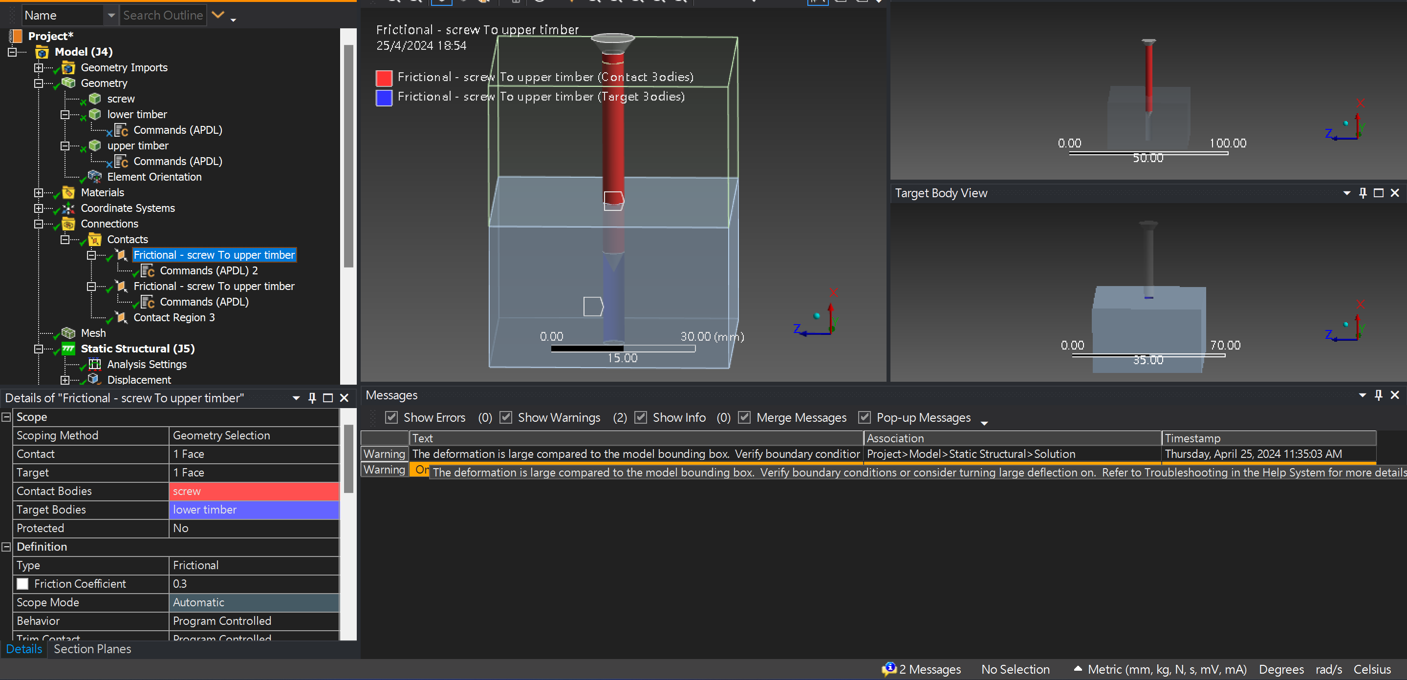
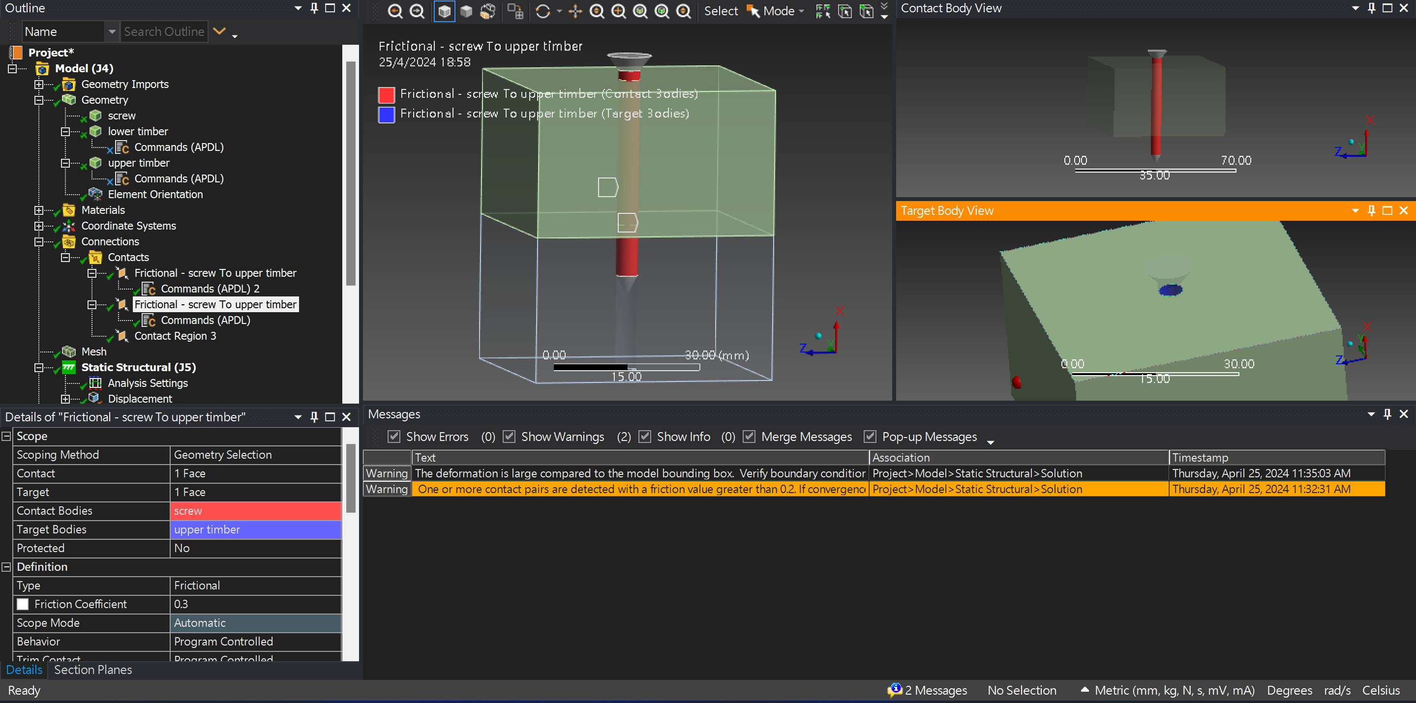
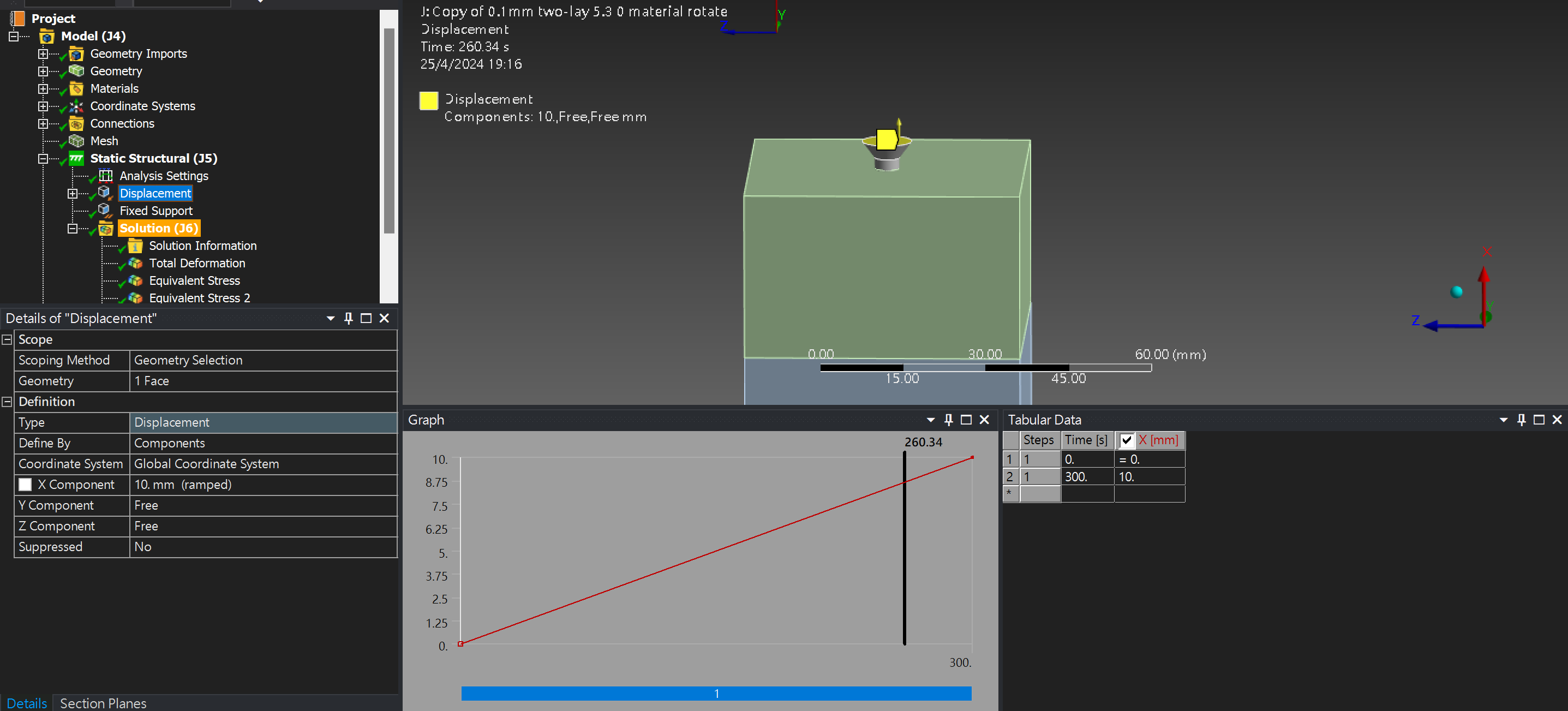
Thank you for replying.This is the contact settings for the frictional contact, the hole is 0.1mm smaller than the screw to create the friction surface? (as far as what I read, the initial value is 1mm but all simulations failed so I changed it to 0.1mm)
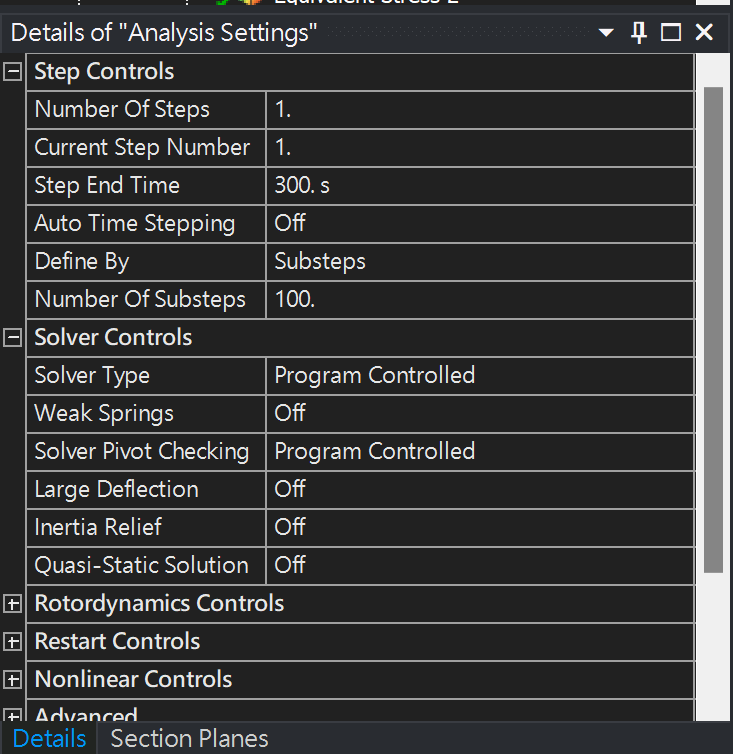
And these are the analysis setting
I added the command snippet as I am trying to create a model that can simulate the result of a pull-out test, to match the experimental result (the orange line in the last graph in my first post, the blue line in that graph represents the simulation result of another program, which used static coefficient = 1.6, dynamic coefficient = 0.3, and decay coefficient = 4. I am using this data as the starting point for my model.)
-
- The topic ‘Dynamic frictional formulation and mesh size’ is closed to new replies.


-
4678
-
1565
-
1386
-
1242
-
1021

© 2025 Copyright ANSYS, Inc. All rights reserved.

