-
-
April 16, 2024 at 2:20 pm
Duru Deniz Arda
SubscriberHi,
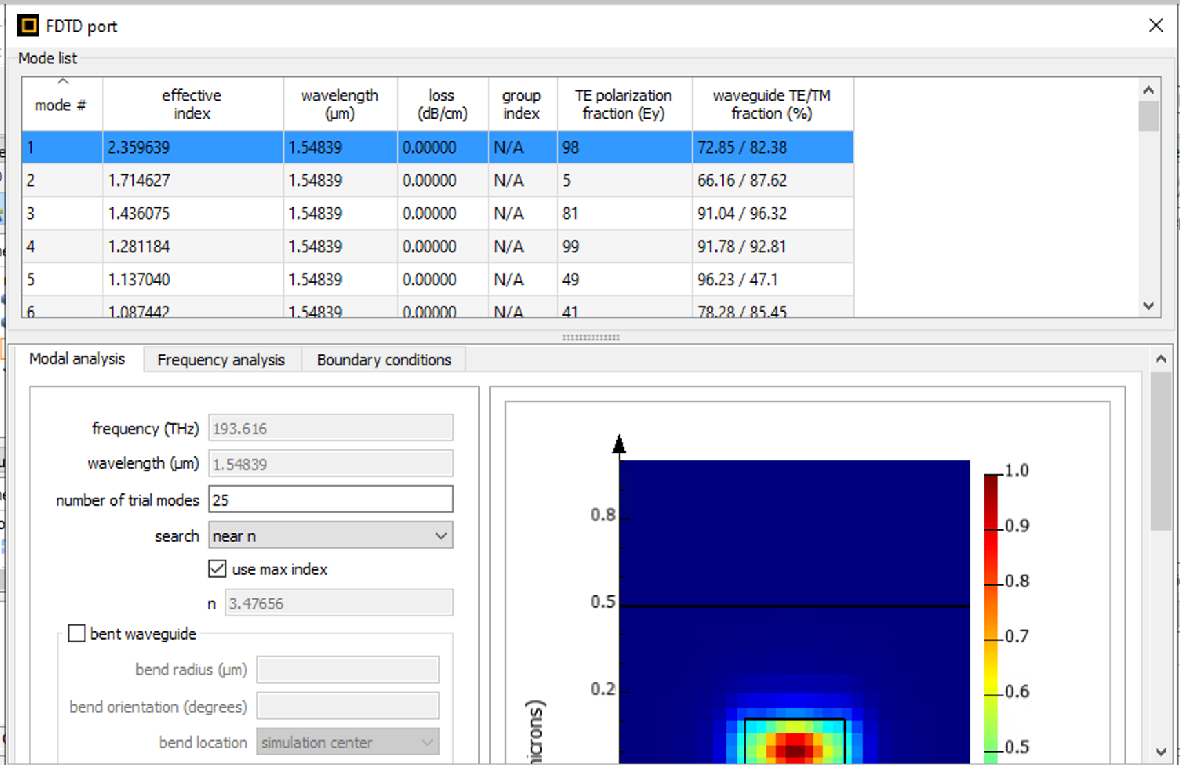
I am working on a straight wg with gaps and I am confused about the losses and the results I viewed with using Interconnect. If I look at the losses from ports, they are always zero. However; using Interconnect I never get 0 loss. With regard to the zero loss on ports, I wonder what is this loss in Interconnect and why they are not same with results from the ports. Also when I have more than 2 ports ( one of course for input) how can I view the losses difference between the ports and the total loss? And can be viewed this totall loss from the last port that I used as an output ? the totall loss is for every kind of loss ? ( I mean if I do consider a bend waveguide, do i see all 3 kinds of losses like propogation, conversion and radiation losses ?)
Thanks in adnvance
Deniz
-
April 19, 2024 at 3:08 pm
Niki Papachristou
Forum ModeratorHi Duru,
Thank you for reaching out to us! May I confirm with you that the case of zero losses that you are discribing, is when simulating your waveguide in MODE?
Kind Regards,
Niki
-
April 19, 2024 at 6:18 pm
-
April 19, 2024 at 7:10 pm
Niki Papachristou
Forum ModeratorHi Duru,
Thank you for your screenshot, this was actually very helpful. I think you are using the FDE solver built in FDTD and the reason that you are not seeing losses in this case is because you are calculating a cross section of your waveguide, while in Interconnect you are measuring the losses of your whole waveguide. Now, for your additional questions, allow me a couple of days to work on them and I will come back.
-
April 20, 2024 at 9:02 am
Duru Deniz Arda
SubscriberHi,
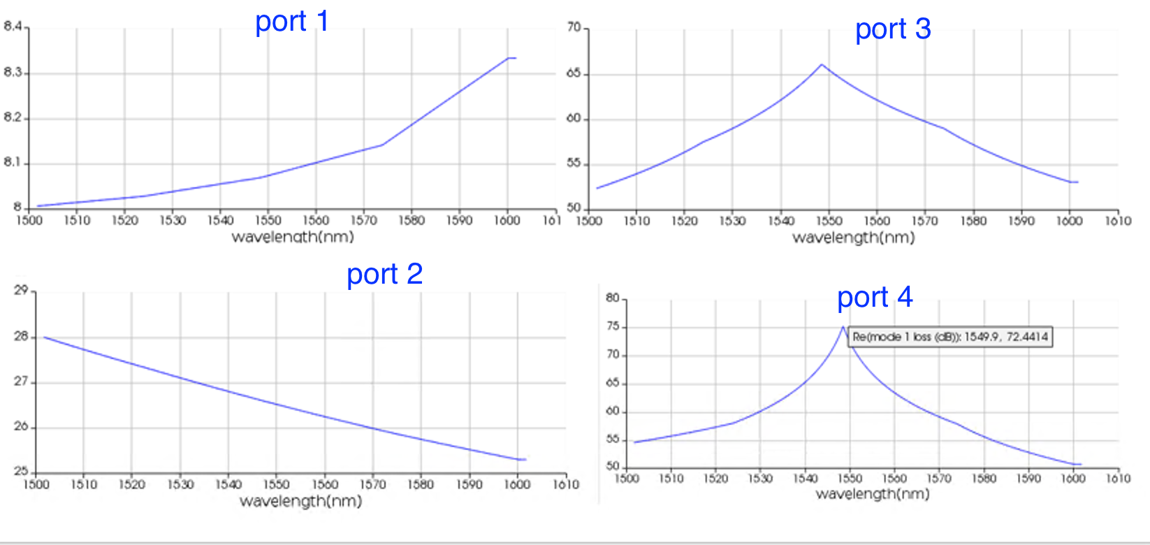
Than can I say the loss from port 1 is the whole loss until coming this port on the wg. If I look at the difference lets say between port 2 and port 3, that would be the loss difference bewteen these two points ? I confused now because I thought the biggest loss comes from the last port kind of the output port on wg but the biggest loss I have viewed is from the very first input port.
Thanks
-
April 22, 2024 at 8:41 am
Niki Papachristou
Forum ModeratorHi Duru,
Thank you for your reaply! I am a little bit confused on the way you are trying to descibe the losses here. Can you please send me a screenshot of your interconnect diagram instead?
Kind Regards,
Niki
-
April 23, 2024 at 3:45 pm
-
- The topic ‘Losses with Ports and Interconnect’ is closed to new replies.


-
4607
-
1510
-
1386
-
1209
-
1021

© 2025 Copyright ANSYS, Inc. All rights reserved.


