TAGGED: -Ansys-Maxwell-electronics
-
-
April 10, 2024 at 5:32 pm
huynguyen33
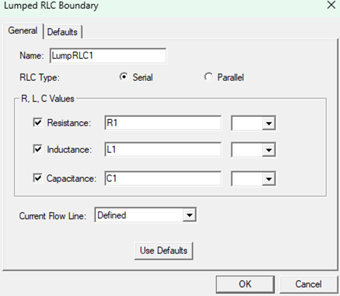
SubscriberHi! I'm trying to simulate for an active reflectarray unit-cell with 2 diodes. The diodes are modelled as lumped RLC components.
In order to realize the 4 modes of the 2 diodes using 1 design, I assigned parameters for the values R and C of each lumped component, and do the parametric sweep. It would be something like this
Mode 00 (R1=0ohm, C1=20fF, R2=0ohm, C2=20fF)
Mode 01 (R1=0ohm, C1=20fF, R2=2ohm, C2=0)
Mode 10...
Mode 11...
The results for the 4 modes when I did this were incorrect (they were all the same), which were different from when I simulated the 4 modes separately and copy paste the data into 1 plot. I'm trying to figure out what went wrong but I have no idea.
Thank you for your help!
-
April 15, 2024 at 1:56 pm
Praneeth
Ansys EmployeeHi Huy Nguyen,
Thank you for reaching out to the Anys learning forum.
It looks like you have tagged Ansys Maxwell for this question. Are you using Ansys Maxwell? Please let us know which design type you are using to help us serve you better.
Best regards,
Praneeth.-
April 15, 2024 at 6:53 pm
huynguyen33
SubscriberHi Praneeth,
Thank you for your reply! I was using Ansys Electronic Desktop 2022 R1.2
Did I tag the wrong product? If so, can you show me how to change that?
Best regards,
Huy Nguyen
-
May 6, 2024 at 6:07 am
Praneeth
Ansys EmployeeHi Huy Nguyen,
Thanks for the reply. Your patience on this query is much appreciated.
Let me rephrase my question - please confirm if you are using HFSS or Maxwell design type of the Ansys Electronics Desktop to help us serve you better.
Best regards,
Praneeth.
-
-
-
- The topic ‘Parametric sweep to realize multiple diode modes Error’ is closed to new replies.


- Three-Phase Voltage Imbalances in dual stator electric generator
- Link the Circuit to 3D Terminals
- Magnetic Dipole moment calculation
- Core Loss in ANSYS MAXWELL Eddy Current solution
- exporting and importing my Netlist for my external circuit
- Error of Metal Fraction in Icepak Classic.
- The unit of theta in Is*sin(2*pi*fre*Time+theta-2*pi/3)
- simplorer-maxwell

-
4628
-
1535
-
1386
-
1215
-
1021

© 2025 Copyright ANSYS, Inc. All rights reserved.


