-
-
April 7, 2024 at 8:20 pm
wei
SubscriberHi there,
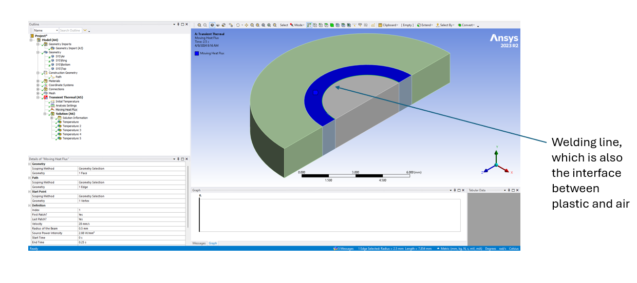
I am modelling the laser welding process using Moving Heat Flux module in Ansys Mechanical.
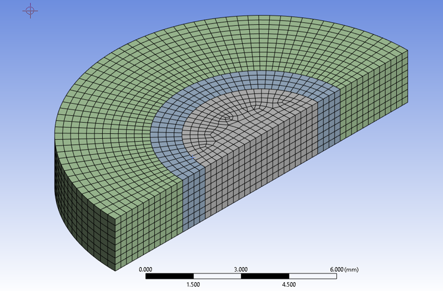
I would like to see the maximum temperature of the welding surface. However, I found the max temperature changes significantly with the mesh element size, even though I have already extensively refined the mesh.
My thoery is that the heat load was applied on the first layer of mesh elements, so smaller the mesh elements lead to higher temperature rise.
May I ask if this is the case? Otherwise I couldn't think of any other reason that the maximum temperature keeps changing with the element size.
Please see my settings and mesh as below. Thank you a lot in advance and please let me know if there is anything unclear.
-
April 8, 2024 at 3:49 pm
dlooman
Ansys EmployeeThat's true in general, but if the time step is small enough the temperature shouldn't keep increasing. Initially there is no gradient through the thickness to conduct the heat so the enthalpy of the element adjacent to the surface determines the temperature. If the element is small the enthalpy will be less. But if the time step is also small, that will reduce the amount of heat and keep the temperature from becoming artificially large.
-
April 9, 2024 at 1:00 am
wei
SubscriberThanks for your reply.
May I ask is there a rule of thumb for setting the time step in modeling? For example, in a CFD world, there is Courant Number to follow?
Also, I am not sure if it is still the time step problem which led to some negative temperature in the first couple dozen steps.
Thank you.
-
April 16, 2024 at 9:06 pm
wei
SubscriberHi Dave,
I tried to alter the time step size, however I found there was almost no effect on the max surface temperature.
-
-
April 9, 2024 at 2:44 pm
dlooman
Ansys EmployeeYes, there is also the problem of too small a time step with higher order elements (producing temperature undershoot.) You might consider using linear, lower order, elements to avoid that issue. I don't know a rule of thumb for setting the time step to capture the correct thermal shock surface temperature. You could determine it experimentally with a test model.
-
April 9, 2024 at 9:41 pm
wei
SubscriberHi Dave,
I tried liner order elements and the negative temperature gone! Thank you so much for that.
I would like to understand more about this temperature undershoot issue. Could you please provide me with some materials to help me understand it better?
Thank you!
-
-
April 10, 2024 at 2:40 pm
dlooman
Ansys EmployeeSee Section 3.4.3.2 of the Thermal Analysis Guide. It's not really an explanation, but it's all we have.
-
April 14, 2024 at 8:39 pm
wei
SubscriberExcuse me where to find "Thermal Analysis Guide"? Thank you
-
-
April 17, 2024 at 2:40 pm
-
- The topic ‘Moving heat flux issue in ANSYS transient thermal’ is closed to new replies.


- LPBF Simulation of dissimilar materials in ANSYS mechanical (Thermal Transient)
- Real Life Example of a non-symmetric eigenvalue problem
- How can the results of Pressures and Motions for all elements be obtained?
- BackGround Color
- Contact stiffness too big
- Element Birth and Death
- Python-Script to Export all Children of a Solution Tree
- Which equations and in what form are valid for defining excitations?

-
4597
-
1495
-
1386
-
1209
-
1021

© 2025 Copyright ANSYS, Inc. All rights reserved.


