-
-
April 2, 2024 at 8:26 pm
N. M.
SubscriberHello everyone,
I am attempting to simulate a case involving the injection of hydrogen into an ambient filled with air.
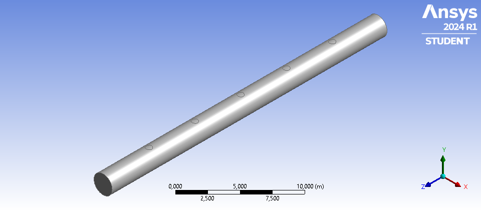
The ambient consists of a cylindrical space, and the hydrogen is introduced through five circular inlets (see Figure 1). The two lateral circular areas of the cylinder serve as outlets.
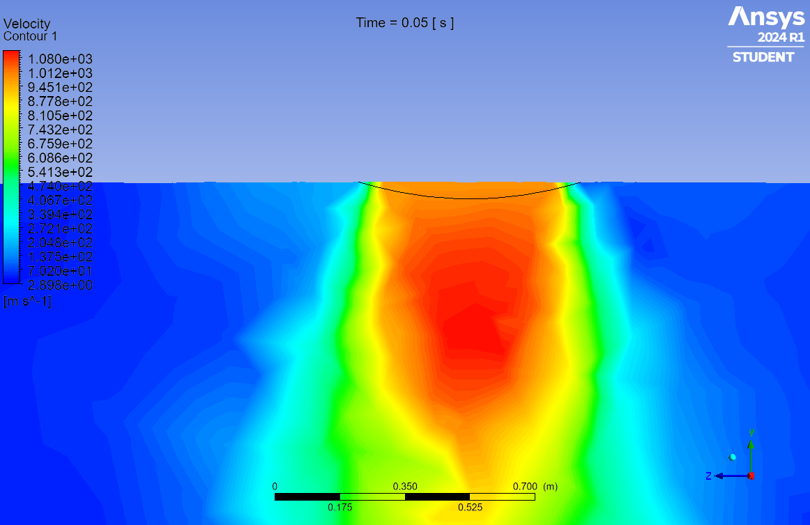
In Figure 2, the velocity contour at the central inlet is depicted. As evident, the fluid velocity is higher at the center and decreases towards the edges of the inlet due to friction.
My objective is to eliminate this friction, aiming to achieve uniform velocity distribution across the entire inlet.
In Fluent, under Setup → Boundary conditions → Wall, I have selected the "Specified Shear" option and set the X-Component, Y-Component, and Z-Component of Shear Stress to zero. However, I have not obtained the desired outcome.
What am I doing wrong?
Thank you. ????
-
April 3, 2024 at 7:21 am
NickFL
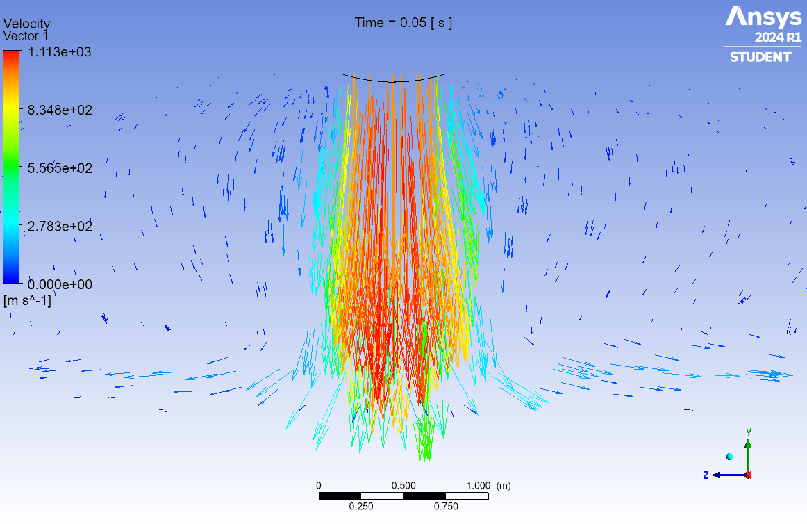
SubscriberCan you show a picture of the velocity vectors across the inlet? Also run reports to find what the min/max values of the velocity at these inlets. Are these as expected?
-
April 3, 2024 at 12:56 pm
N. M.
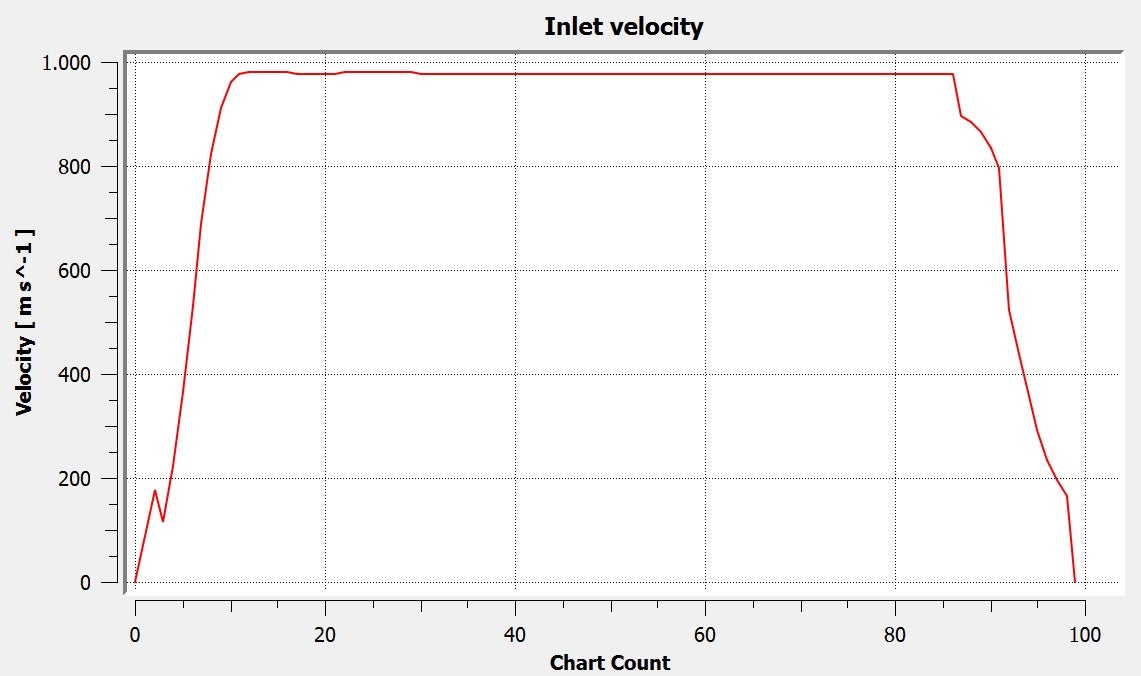
SubscriberThe first figure depicts the vectors, while the second one illustrates a plot of the velocity along an axis situated in the YZ plane, extending from one end to the other of the circular inlet (Figure 3, the yellow line at the top). As evident, the velocity begins at 0 at the inlet boundary and reaches the specified value of 980 m/s in the central region of the inlet. My objective is to ensure that the velocity maintains a constant value of 980 at every point within the inlet.
Thank you.
-
-
April 3, 2024 at 10:13 am
Rob
Forum ModeratorPlease can you also replot the image with node values off too - given the inlet speed you're going to need a significant amount of mesh to resolve the velocity gradients.
-
April 3, 2024 at 12:57 pm
N. M.
SubscriberSorry, I don't quite understand what you're asking for. Are you requesting a detailed view of the mesh near the inlet?
-
April 3, 2024 at 1:46 pm
Rob
Forum ModeratorYes, but if you plot the contour in Fluent (unless you used CFX) you can plot with node values on (smooth contour) or off (cell values) which highlights the mesh resolution on the velocity gradients. 1000m/s is fairly rapid!
-
-
-
- The topic ‘No friction at inlet’ is closed to new replies.


-
4613
-
1530
-
1386
-
1209
-
1021

© 2025 Copyright ANSYS, Inc. All rights reserved.


