-
-
April 2, 2024 at 12:59 pm
isabel.prestes
SubscriberDear Ansys Forum community,
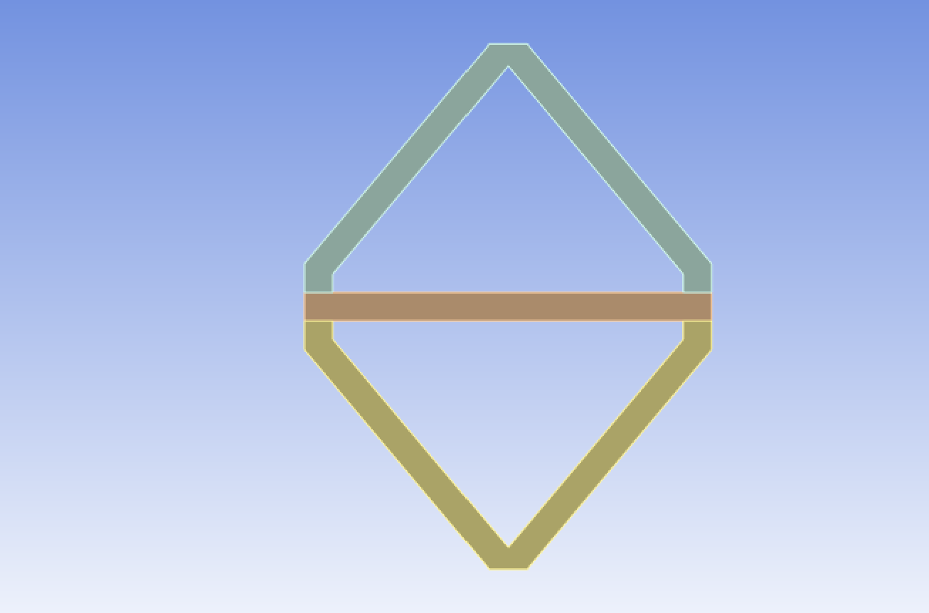
I am performing static structural simulations of structures, that look like this:
A thermal condition is applied in the three parts shown and I evaluate the deformation of the structure at the end.
However, these structures represent unit cells of a larger one. So, in theory, I would have several unit cells around this one that I am simulating.
This should have an impact in the deformation, since the unit cells around may restrict the movement of the single unit cell.
I would like to apply a periodic boundary condition, so the software could simulate, as if there were several unit cells around the one I modelled, without having to model a structure with several unit cells. Is it possible?
Thank you!
-
April 4, 2024 at 6:11 pm
-
April 5, 2024 at 2:08 pm
isabel.prestes
SubscriberHi mjmiddle,
Thanks, it seems indeed that this should solve my problem.
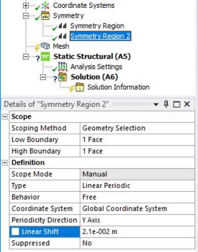
The unit cells should be touching each other, so the distance between them should be zero. However, I cannot set it as zero in the linear shift. Or should I give the height of my structure as the shift?
-
April 5, 2024 at 5:13 pm
mjmiddle
Ansys EmployeeThe unit cell would never make sense at zero. It is the distance you would use if you were copying the geometry so that the copied bodies line up exactly with the original bodies. It is the vertical and horizontal distance of your geometry shown above.
-
April 8, 2024 at 1:19 pm
isabel.prestes
SubscriberThe linear periodic symmetry regions worked perfectly when they were configured separately. So, either periodic symmetry in Z-axis or in X-axis. The results also make sense, because the faces, where the unit cells would be in contact to the one I am simulating do not bend, as it happened to the unit cell alone, without any symmetry region set.
However, whenever I try to simulate the unit cell with both periodic symmetry in Z- and X-axis, a question mark appears in the static structural and solution tabs. Moreover, I get the following error message: "You have incorrectly defined multiple symmetry objects. The solution cannot proceed unitl this is fixed."
Any idea of what could be done?
-
April 9, 2024 at 4:36 am
mjmiddle
Ansys EmployeeMy apologies, the linear periodic is only supported in one direction. Refer to post:
/forum/forums/topic/linear-periodic-bcs-in-both-x-and-z-directions-causing-meshing-error/
You can try using a frictionless support on the boundaries of the other direction. This sets up essentially the same constraints as a mirror condition in a structural analysis. A mirror condition is not the same as linear periodic but it may suffice depending on the loading.
-
- The topic ‘Input periodic boundary conditions in a unit cell’ is closed to new replies.


-
5044
-
1754
-
1387
-
1248
-
1021

© 2026 Copyright ANSYS, Inc. All rights reserved.


