TAGGED: 3DFDTD, polarization
-
-
April 2, 2024 at 11:31 am
-
April 2, 2024 at 5:33 pm
Guilin Sun
Ansys Employee你是用的LC Attribute,还是直接设置的双折射材料?确认偏振改变需要超过 2pi 的位相?是不是其它倍数会好一点呢?检查一下理论。
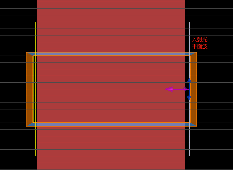
检查一下液晶折射率是否设置到整个结构中,随着厚度增加折射率按预定的规律变化?
增加厚度是如何进行的?选了几个数值还是扫描?监视器位置是否也跟着移动?
确认光源的偏振方向与设置的快慢轴一致,能够产生所需要的双折射。
-
April 3, 2024 at 12:42 am
Tanbin Shao
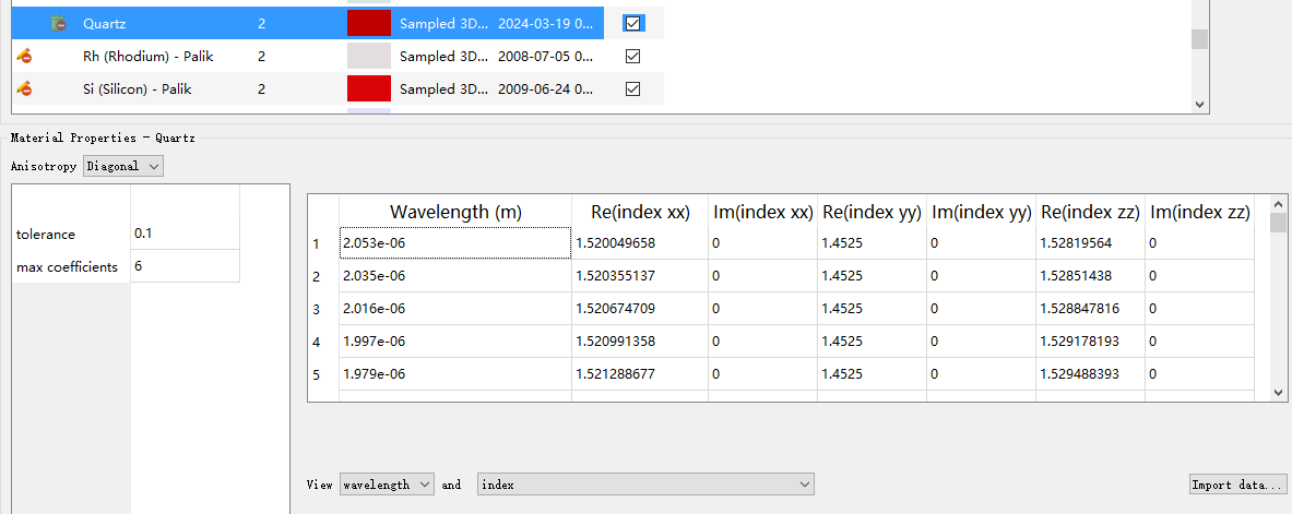
Subscriber新建的石英材料,导入3d折射率,直接设置LC材料。
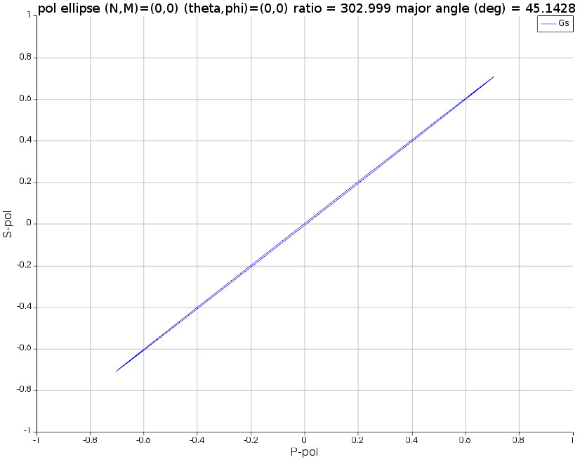
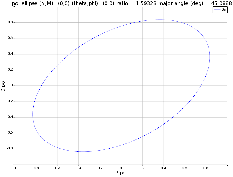
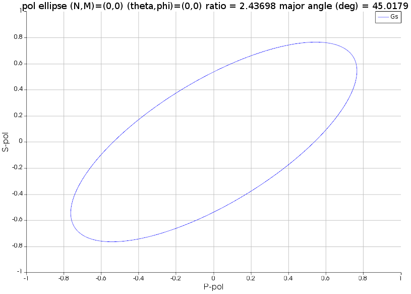
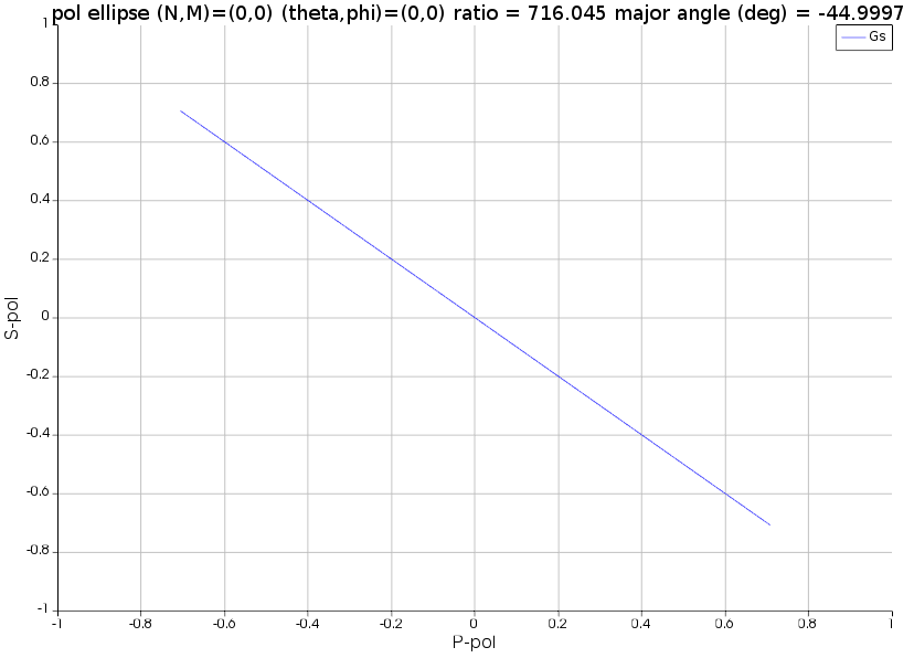
希望观察到液晶厚度足够大时,双折射相位足够大。
选了数值增加厚度。
-
April 3, 2024 at 3:06 pm
Guilin Sun
Ansys Employee你按我的建议检查了吗?
你的描述有点矛盾:已经导入3d折射率,为什么还要直接设置LC材料?LC必须用Attribute设置其折射率变化,你现在只是一个材料为什么会有两种呢?
导入的材料足够长吗?随你改变的长度而变吗?我感觉这个3D折射率长度固定了,因此你改变厚度位相几乎不变。
你再琢磨一下。
-
April 4, 2024 at 5:18 am
-
Viewing 4 reply threads
- The topic ‘液晶调整出射光偏振态时厚度受限’ is closed to new replies.
Innovation Space


Trending discussions


Top Contributors


-
5094
-
1830
-
1387
-
1248
-
1021
Top Rated Tags


© 2026 Copyright ANSYS, Inc. All rights reserved.
Ansys does not support the usage of unauthorized Ansys software. Please visit www.ansys.com to obtain an official distribution.

