-
-
March 14, 2024 at 12:39 pm
1092395923
Subscriber我是参考ring-modulator这个案例来仿真调制器的,已经可以得到谐振峰随电压的偏移,然后就计划仿真时域下的调制眼图,参考的是案例ring-modulator-time-domain-interconnect。
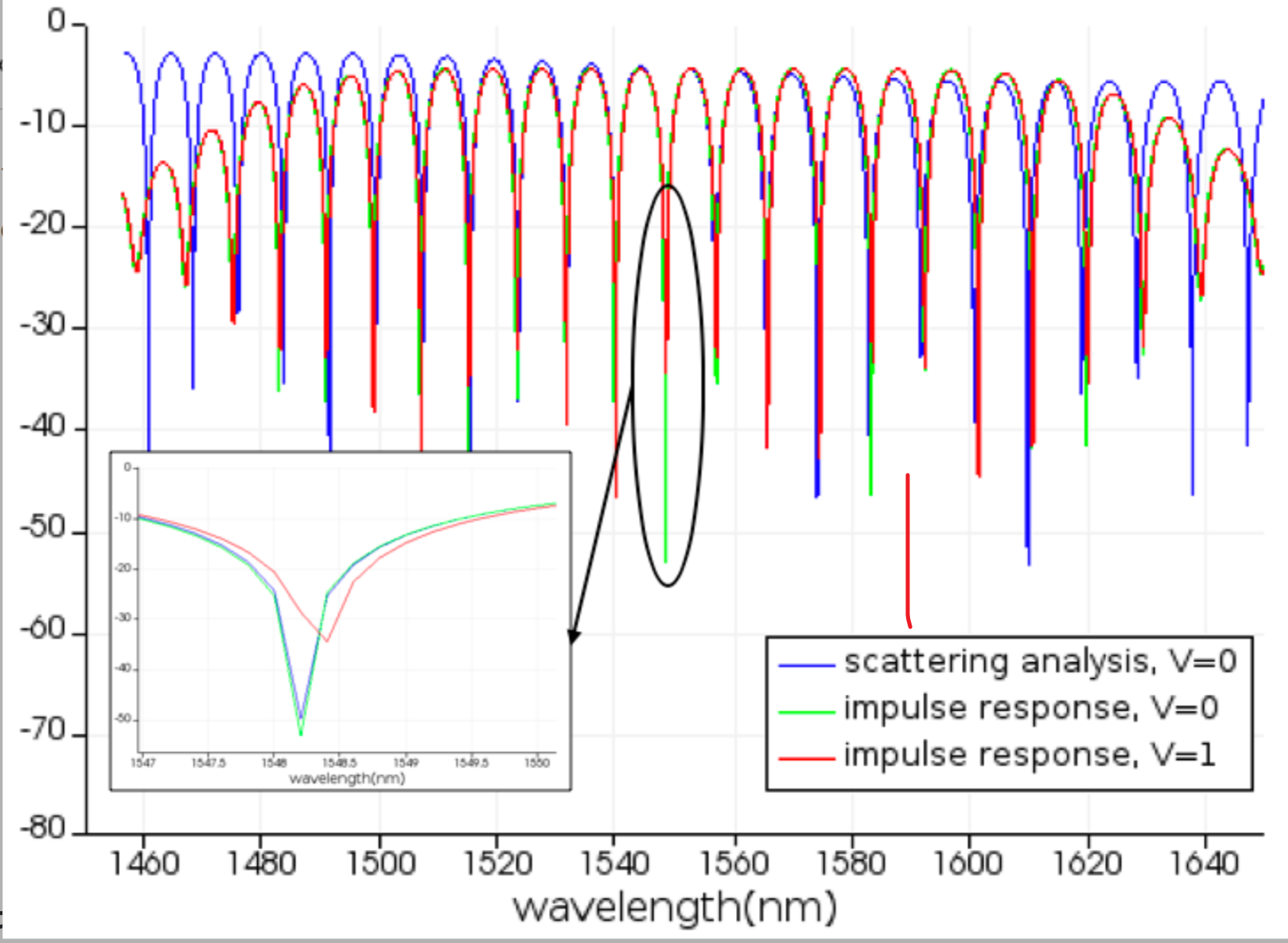
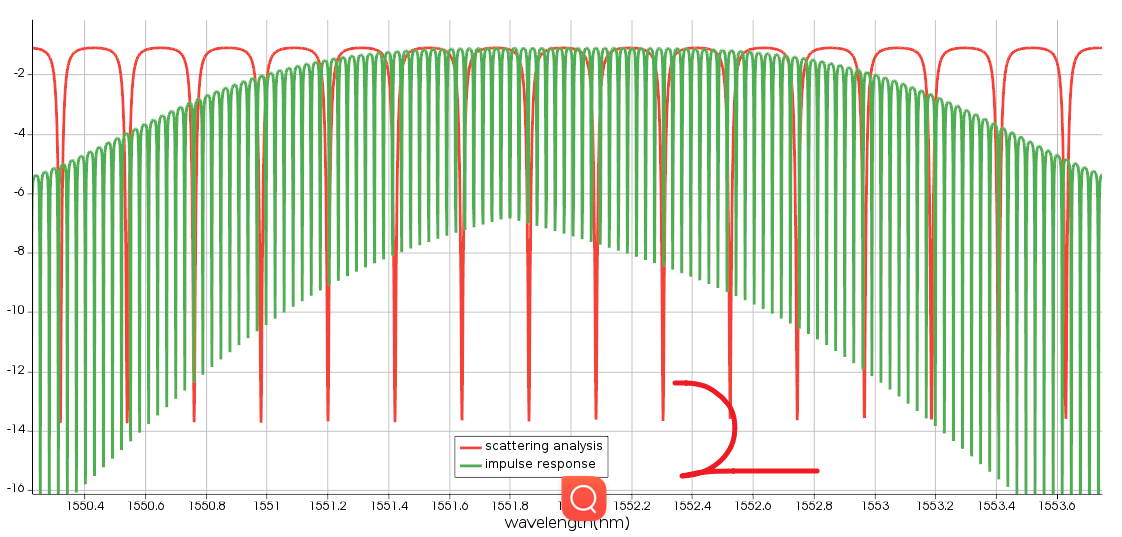
案例中第一步是validate impulse response (time-domain) and scattering analysis (frequency domain) results 。正确结果应该是图1(时域和频域在中心频率处的曲线基本吻合)。但是我得出的结果是图2,在impulse response的曲线中,出现了很密集的谐振峰,请问是哪里出现问题了吗?
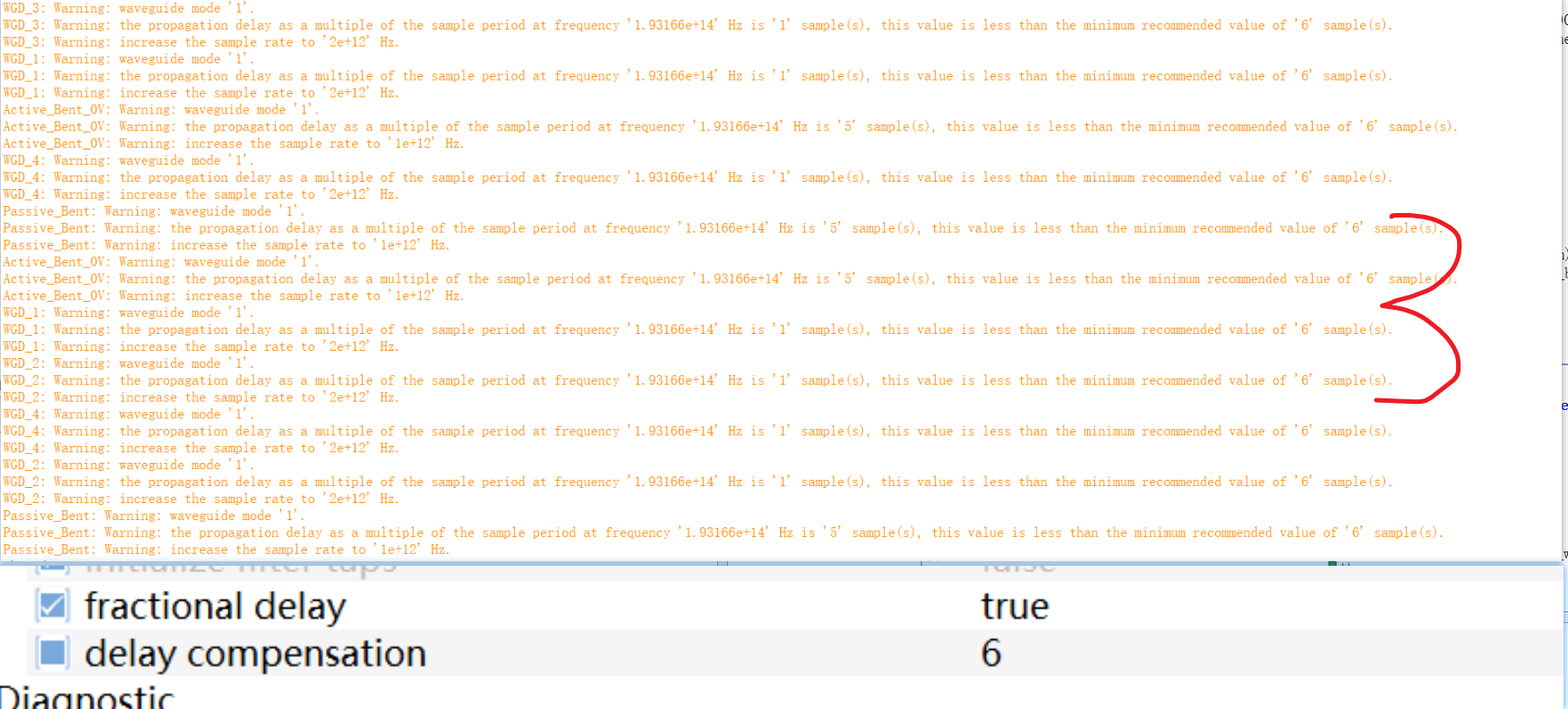
图3为输出的警告,波导元件中delay compensation尝试了好几个数值都不太行。
谢谢!
-
March 14, 2024 at 6:58 pm
Guilin Sun
Ansys Employee会不会是ring的直径太大了?请先从小直径开始测试,即两个直波导和补偿波导的长度。
你测试网上例子没问题吧?你把环形谐振腔中三个波导的长度都增加10倍看看结果如何。
例子都是经过测试调整才得到良好结果的,不是随便添加器件任意参数都能给出所需要的结果。
“Delay compensation and fractional delay are enabled in the Straight Waveguide models to makes sure the time domain result matches the frequency domain result in the bandwidth of interest. ”
-
Viewing 1 reply thread
- The topic ‘调制器时域仿真问题’ is closed to new replies.
Innovation Space


Trending discussions


Top Contributors


-
4803
-
1576
-
1386
-
1242
-
1021
Top Rated Tags


© 2026 Copyright ANSYS, Inc. All rights reserved.
Ansys does not support the usage of unauthorized Ansys software. Please visit www.ansys.com to obtain an official distribution.


