-
-
March 12, 2024 at 4:35 pm
pnair
SubscriberHello,
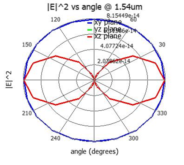
I am working on the farfield simulations using a dipole source on a SiC thin film. I have a question related to the polar plots generated for different dipole orientation using the Scat_ff analysis group. This is the polar plot generated for a dipole source with phi=0 and theta = 0 and the orientation of the dipole is along Z-axis
But from the theory/text books, this is what i understood about the radiation pattern of the dipole along the z-axis
So, From the textbooks, if we consider a x-z plane, maximum radiation intensity for theta=90 and this matches with how we are see from a spherical coordinate system with theta is the between Z-axis and x-y plane.. But in the polar plots generated, for theta = 90 (i have assumed the angles in polar plot as theta)radiation intensity is maximum.
I am concerned about the x-y axis of the polar plot and what is angle represented in polar plt?
So, if its theta, I am assuming it should start from 0 degree in the top along z-axis and 90 degree perpendicular to the z-axis. Please help regrading this.
Thanks,
Prabha
Â
-
March 12, 2024 at 7:30 pm
Guilin Sun
Ansys EmployeePolar plot does not have x-y. The simulation results shows two planes: one is the xy and the other is xz (yz omiited). The actual 3D radiation pattern is donut shape. Thus depending on the cut you will see different polar radiaiton pattern.
along the polarization direction the farfield is zero. In the perpendiuclar plane it is circle.
The angle showing in the above plots is phi, from 0 to 360 deg.
Â
Â
Â
-
March 12, 2024 at 8:06 pm
pnair
Subscriber -
March 12, 2024 at 8:34 pm
pnair
SubscriberCan you please explain how the xz plane in the above-mentioned polar plot is created ? Based on my understanding, it is created by keeping phi=0 and phi = 180 constant in a 3D polar radiation plot and theta varying from 0 to 180 degrees. But, I would like to know if this angle is phi, how it can be used to plot both XZ planes and XY planes?
-
March 13, 2024 at 4:00 pm
-
- The topic ‘Regarding farfield radiation patterns’ is closed to new replies.
- Import material .txt file with script
- Errors Running Ring Modulator Example on Cluster
- Absorption cross-section of AuNR excited by prism-based TIR
- How to measure transmission coefficients on a given plane .
- TE Polarization Fraction + Waveguide TE/TM Fraction
- Edge Coupler EME Example Issue
- Lumerical Python API Topology Optimization Error 2025 R1
- 2D inverse design grating coupler
- FDE : Simulation waveguides with electrodes
- Loss of lithium niobate phase modulator
-
2262
-
925
-
599
-
591
-
497
© 2025 Copyright ANSYS, Inc. All rights reserved.